LC resonance filters (AQA A-Level Physics): Revision Notes
13.3.1 LC resonance philtres
Overview of LC Resonance Philtres:
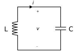
A filter is an electrical circuit that selects a particular frequency or range of frequencies from an AC (alternating current) input signal, which is important in applications like radio receivers to isolate specific broadcasts. The LC resonance filter achieves this filtering effect by using an inductor (L) and a capacitor (C) arranged in parallel.
- Inductor (L) - A coil of wire that opposes changes in current by generating a magnetic field and storing energy.
- Capacitor (C) - A component that stores electric charge and releases it as current, forming an electric field across its plates.
Electromagnetic Induction in LC Circuits:
The operation of an inductor in an AC circuit is based on:
- Faraday's Law: The induced electromotive force (emf) is proportional to the rate of change of magnetic flux.
- Lenz's Law: The direction of induced current will oppose the change causing it. As the alternating current (AC) passes through the inductor, it creates an alternating magnetic field around it, which generates an emf in the opposite direction of the current (as per Lenz's Law). This is crucial for understanding the oscillatory behaviour of an LC circuit.
Functioning of an LC Circuit:
An LC circuit works in an oscillating manner, cycling energy between the electric field in the capacitor and the magnetic field in the inductor. Here's how it functions:
- Charging the Capacitor:
- A power source charges the capacitor. Once charged, the power source disconnects, and electrostatic potential energy is stored across the capacitor plates.
- Energy Transfer to Inductor:
- When the capacitor begins to discharge, current flows through the inductor. The capacitor's potential energy decreases as it transfers to the inductor, which begins to store energy in a magnetic field.
- Oscillatory Behaviour:
- Once the capacitor is fully discharged, the energy stored in the magnetic field of the inductor induces a current in the opposite direction, recharging the capacitor. This process continues back and forth, creating oscillations within the circuit.
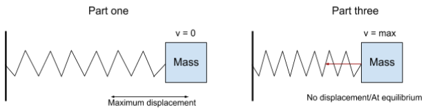
- Analogous to a Mass-Spring System:
- An LC circuit behaves like a mass-spring system, where mass represents inductance (L) and the spring represents capacitance (C). In this analogy:
- At maximum displacement (fully charged capacitor), all energy is stored as potential energy.
- At maximum speed (fully charged inductor), all energy is stored as kinetic energy in the magnetic field.
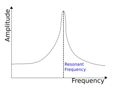
Resonance and Natural Frequency:
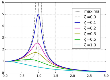
The driving force for an LC circuit is an external alternating emf source. When this source matches the natural frequency of the LC circuit, resonance occurs, leading to maximum oscillation amplitude.
- Natural/Resonant Frequency :
where is inductance, and is capacitance. The unit of frequency, if is in henries () and in farads (), is hertz ().
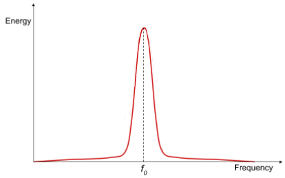
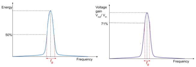
Energy Response Curve and Effect of Resistance:
- An energy response curve shows energy variation in an LC circuit as frequency changes. At resonance frequency , the stored energy is maximal.
- Damping (electrical resistance) reduces oscillations, causing:
- A shift in resonance frequency (moves left on a graph).
- Reduced amplitude of maximum oscillation.
- Broadened resonance peak as damping increases.
Bandwidth and Quality Factor (Q-Factor):
- Bandwidth - The range of frequencies where energy is at least % of the maximum.
- Q-Factor - Measures how sharp the resonance peak is:
A high Q-factor indicates a narrow bandwidth with less noise, while a low Q-factor means a broader bandwidth with more noise and energy losses.
- High Q-factor filter: Better frequency selectivity, suitable for applications like radio tuners.
- Low Q-factor filter: Broader bandwidth, suitable where a wider frequency range is acceptable.