Inverting amplifier configuration (AQA A-Level Physics): Revision Notes
13.4.1 Inverting amplifier configuration
Inverting Amplifier Configuration:
In an inverting amplifier configuration, the output voltage from the operational amplifier (op-amp) is fed back into the inverting input. This forms a closed-loop circuit with negative feedback, allowing for control over the amplifier's gain.
Since negative feedback stabilises the output, this configuration makes it possible to set the op-amp's gain to much lower values, which is useful for controlling the amplification of signals.
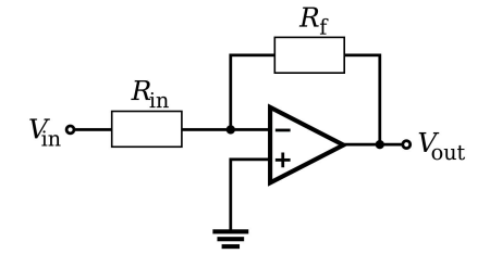
Circuit Diagram Explanation:
- The inverting amplifier circuit contains a resistor at the input and a feedback resistor connected between the output and the inverting input.
- Power supply connections (not shown in the diagram) are assumed to be present in most amplifier circuits.
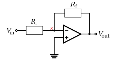
Virtual Earth Concept and Derivation:
- Virtual Earth Analysis:
- In this configuration, the non-inverting input is grounded ( V). Due to the properties of an ideal op-amp, the open-loop gain (denoted as ) is assumed to be infinite.
- This leads to the condition where the voltage at the inverting input is effectively V, called a virtual earth (or virtual ground). Although not physically connected to earth, this point is close to V due to the infinite open-loop gain.
- Transfer Function Derivation:
- Using Kirchhoff's Current Law (KCL), which states that the total current entering a junction is equal to the current leaving the junction, we can determine the relationship between input and output voltages.
- Because of the virtual earth, the input current through (from ) to the inverting input) is equal to the feedback current through (from the inverting input to ). Using Ohm's law, we have:
Since , we can write:
Rearranging, the gain (transfer function) of the inverting amplifier is given by:
This negative sign indicates inversion of the input signal's polarity.
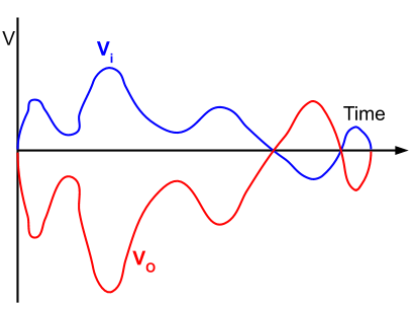
Graph of Input and Output Voltages:
The graph of the output voltage versus time shows that the output is an inverted (mirrored along the x-axis) and amplified version of the input voltage .
- Inverted Polarity: The negative sign in the gain equation reflects that the output waveform is 180° out of phase with the input.
- Reduced Distortion: The inverting configuration provides lower distortion compared to non-inverting configurations, as it benefits from stabilisation due to the virtual earth.
Key Takeaways:
- Gain: The gain of an inverting amplifier is set by the ratio .
- Phase Inversion: The output voltage is an inverted version of the input signal.
- Virtual Earth: The virtual earth condition simplifies analysis and provides stabilisation by ensuring the inverting input remains close to V.
- Applications: Commonly used in audio processing and signal conditioning, where controlled amplification with minimal distortion is desired.