Combinational logic (AQA A-Level Physics): Revision Notes
13.5.1 Combinational logic
Logic gates are fundamental components in digital electronics. They are electronic switching circuits that output different signals depending on the combination of their inputs, which can either represent On (, indicating current flow) or Off (, no current flow). These gates are crucial in processing digital information and are widely used in devices like computer processors.
- On () – Indicates the presence of a current.
- Off () – Indicates the absence of a current.
Combinational Logic
When several logic gates are combined to produce a specific output based on the inputs, this setup is called combinational logic. The output depends solely on the current input values, without any memory of previous inputs. Combinational logic is essential for analysing and creating digital circuits with desired functionalities.
Truth Tables
To understand how a combination of inputs affects the output, truth tables are used. A truth table lists all possible input values and the corresponding output for each input combination. This is particularly helpful for simplifying and analysing digital circuits. For a circuit with inputs, there are possible input combinations. For example, with 4 inputs, there are combinations.
Types of Basic Logic Gates
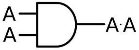
- AND Gate
- Output is only if both inputs are ; otherwise, the output is .
- Truth table:
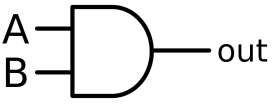
| A | B | Out |
|---|---|---|
| 1 |
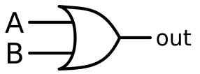
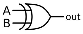
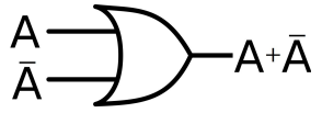
- OR Gate
- Output is if either input is ; otherwise, the output is .
- Truth table:
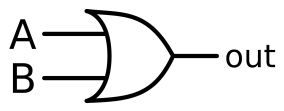
| A | B | Out |
|---|---|---|
- NOT Gate
- Inverts the input; output is if input is , and vice versa.
- Truth table:
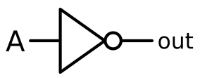
| A | Out |
|---|---|
| 1 | |
| 0 |
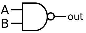
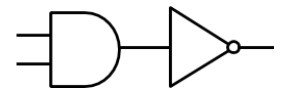
- NAND Gate
- Output is only if both inputs are ; otherwise, the output is .
- This gate is essentially an AND gate followed by a NOT gate.
- Truth table: | A | B | Out | |---|---|---| | | | | | | | | | | | | | | | |
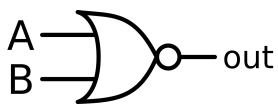
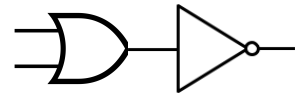
- NOR Gate
- Output is only if both inputs are ; otherwise, the output is .
- This gate is essentially an OR gate followed by a NOT gate.
- Truth table: | A | B | Out | |---|---|---| | | | | | | 1 | | | | 0 | | | | 1 | |
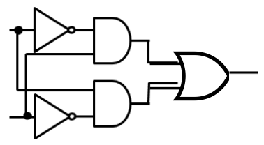
- EOR (XOR) Gate
- Exclusive OR gate gives an output of if one input is and the other is .
- Often used as a comparator.
- Truth table: | A | B | Out | |---|---|---| | | 0 | | | | 1 | | | | 0 | | | | 1 | |
Boolean Algebra and Logic Circuit Simplification
Boolean algebra is a mathematical tool used to describe and optimise logic circuits. Using Boolean algebra, complex circuits can be represented with expressions, and unnecessary gates can be eliminated.
Key identities in Boolean algebra:
- AND:
- OR:
- NOT:
Key Boolean Laws
- Associative Law
- (
- Commutative Law
- Distributive Law
- = + (
Simplifications
- These simplifications allow circuits to be designed with fewer gates, saving space and power.
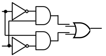
Example: Drawing Logic Circuits
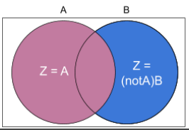
Given a truth table or Boolean expression, you can construct a logic circuit. For example, to simplify + ($$\overline{A} \cdot B), use:
- Identify gates required: Two AND gates, two NOT gates, and one OR gate.
- Connect gates as per the Boolean expression.
- Draw the circuit accordingly, ensuring each gate output is linked correctly.
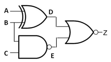
Example: Creating a Truth Table
For a circuit:
- Label intermediate signals.
- Create a truth table listing all input combinations.
- For each row, evaluate intermediate signals and final output.