Alternating currents (AQA A-Level Physics): Revision Notes
📚 Revision Notes
7.5.5 Alternating currents
Alternating Current (AC) and Electromagnetic Induction
-
When a coil rotates in a magnetic field, an electromotive force (emf) is induced due to the interaction between the magnetic field and the rotating coil.
-
This induced emf can be calculated using:
Where:
- is the magnetic flux density,
- is the area of the coil,
- is the number of turns in the coil,
- is the angular speed of the coil, and
- is time.
- The sine function indicates that the emf is alternating, meaning its direction changes over time as the coil rotates.
Understanding Oscilloscope Displays for AC and DC Currents
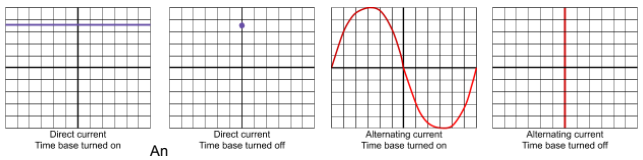
- An oscilloscope can display variations in voltage over time, useful for analysing both alternating and direct currents.
- The time-base setting controls the horizontal axis, showing how voltage changes over time:
- With time-base on: All voltage variations are visible, displaying an AC waveform as a sinusoidal wave and DC as a straight line.
- With time-base off: All voltages are displayed at once, showing AC as a vertical line and DC as a dot on the screen.
- Adjusting the Y-gain (for voltage) and time-base (for time intervals) makes measurements easier.
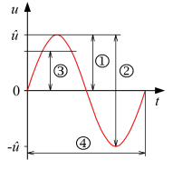
AC Waveforms and Measurements
- Peak Voltage : The highest point of the waveform from the zero or equilibrium position.
- Peak-to-Peak Voltage: The voltage difference from the highest to the lowest point of the waveform.
- Root Mean Square (RMS) Voltage: The effective voltage value of an AC supply. For a sinusoidal wave:
Similarly, the RMS current:
- Time Period (T): The time taken for one complete oscillation or cycle of the wave. The frequency () is the reciprocal of the time period:
infoNote
Worked Example: Calculating UK Mains Voltage Peak
- The UK mains supply is approximately V (this is the RMS voltage).
- To find the peak voltage from the RMS:
- Peak-to-Peak Voltage would be double the peak voltage: