I–V Graphs (AQA GCSE Physics Combined Science): Revision Notes
2.1.6 I–V Graphs and Resistors
Types of Resistors
The I-V graph for a resistor can be used to compare different resistors. In an I-V graph, the current is on the y-axis and the potential difference is on the x-axis. The gradient of the graph represents the resistance which can be calculated at any point on the graph by reading the potential difference and current at that point and calculating the resistance using the formula below:
Formula
- = resistance in ohms (Ω)
- = potential difference in volts (V)
- = current in amps (A).
Different types of resistors and components have different characteristic I-V graphs. The three main types of resistors are:
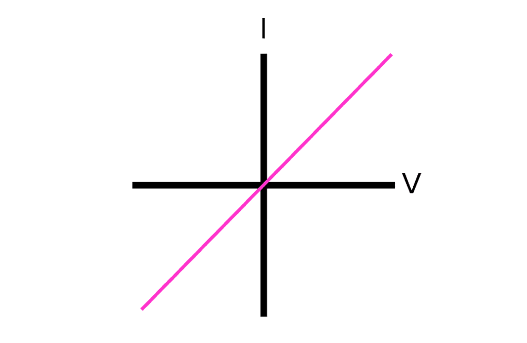
Ohmic Resistors:
If the current and potential difference are directly proportional (a straight line through the origin) the resistor is said to be ohmic.
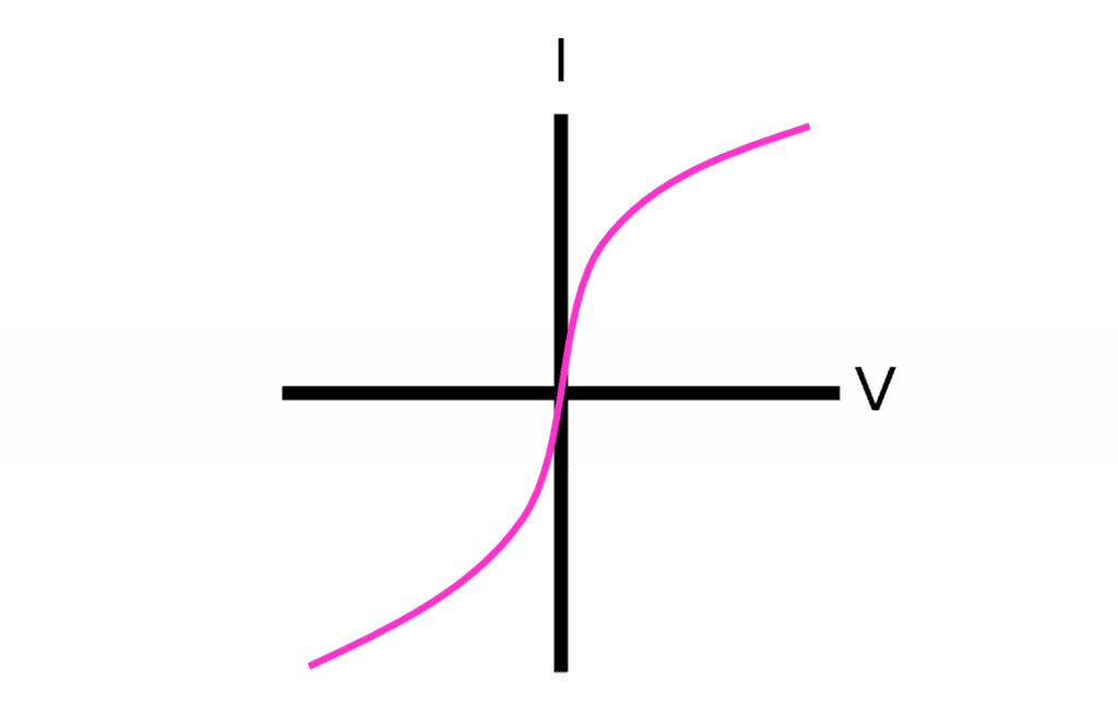
Non-ohmic Resistors:
The resistance of some resistors and other circuit components such as lamps change depending on the current across the resistor or component. This is because when the current increases, the wire gets hot and the metal atoms in the wire vibrate, causing more resistance. Such components are called non-ohmic.
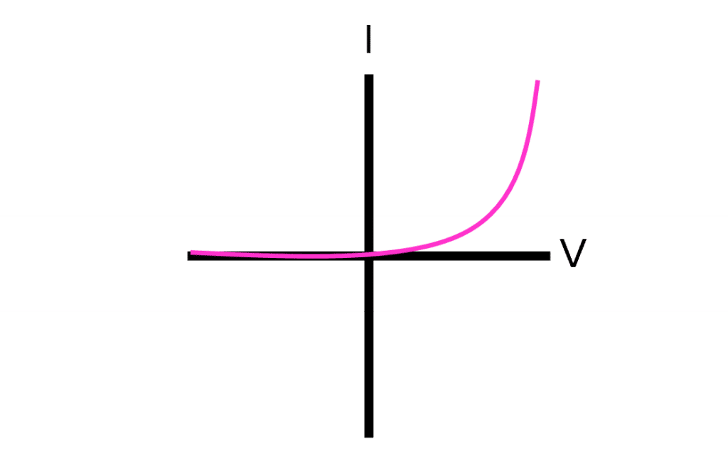
Diodes:
Diodes allow current to flow in one direction only and only when the potential difference has reached a threshold voltage. Above the threshold voltage the resistance drops rapidly and the current increases rapidly. In the direction opposite to the allowed flow through the diode, resistance remains very high for all values of potential difference.