Network Flow Problems (HSC SSCE Mathematics Standard): Revision Notes
Network Flow Problems
Introduction to network flow problems
Network flow problems are practical applications of directed graphs that model the movement of materials through a system. These problems involve analysing how something flows from a starting point (the source) to an ending point (the sink).
Common real-world examples include:
- Water flowing through pipe systems
- Traffic moving along one-way roads
- Data travelling through computer networks
- Goods being transported through supply chains
The basic structure follows this pattern:
source → flow through network → sink
In network flow problems, we use directed graphs where:
- Vertices (nodes) represent locations or junctions
- Edges represent the connections between locations
- Weights on edges represent the capacity - the maximum amount that can flow through that connection in a given time period
The source is similar to the "start" in critical path analysis, whilst the sink is like the "finish". This connection helps you apply knowledge from other graph theory topics.
Understanding maximum flow
When materials flow through a network, the maximum possible flow is limited by the smallest capacity along any path. This is known as the bottleneck principle.
Flow through pipes in series
Consider two pipes connected one after the other. The first pipe can carry litres per minute, whilst the second can carry litres per minute.
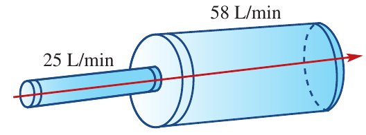
Even though the larger pipe has a capacity of litres per minute, it can only receive litres per minute from the smaller pipe. The overall system is limited to litres per minute.
When an edge operates at its maximum capacity, we say it is saturated. The larger pipe has excess flow capacity (spare capacity that isn't being used), similar to float time in critical path analysis.
The bottleneck effect
If we reverse the arrangement and connect the large pipe before the small pipe, we create a bottleneck at the junction.
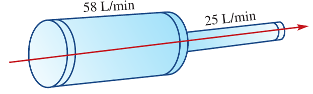
The large pipe delivers litres per minute to the junction, but the small pipe can only accept litres per minute. Material would build up at the junction. Again, the system's maximum flow is litres per minute.
Maximum flow principle
Key Principle: When pipes or pathways of different capacities are connected in series (one after the other), the maximum flow through the entire system equals the capacity of the smallest individual pipe or pathway.
This principle applies whether the small capacity comes first or last in the sequence. The smallest capacity always determines the maximum flow for that path.
Worked example: Calculating maximum flow in traffic networks
Worked Example: Traffic Network Maximum Flow
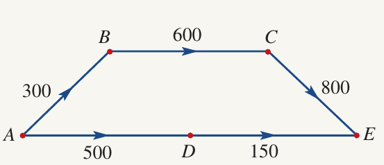
Problem setup
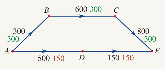
The diagram below shows a traffic network connecting towns A, B, C, D, and E. The numbers on the edges represent the maximum number of cars per hour that each road can carry. All roads are one-way only.
We need to find:
- The maximum traffic flow from A to E through town C
- The overall maximum traffic flow from A to E
- The effect of adding a new road
Solution part (a): Flow through town C
To find the maximum flow through town C, we examine the path A→B→C→E.
Looking at each road's capacity:
- A to B: cars per hour
- B to C: cars per hour
- C to E: cars per hour
The smallest capacity is cars per hour (road A→B). Therefore, the maximum flow through this path is cars per hour.
At maximum flow, road A→B is saturated, whilst roads B→C and C→E have excess capacity.
Answer: The maximum traffic flow from A to E through town C is 300 cars per hour.
Solution part (b): Overall maximum flow
Now we consider all possible paths from A to E. We've already found that path A→B→C→E can carry cars per hour.
There's another path: A→D→E.
Looking at this path's capacities:
- A to D: cars per hour
- D to E: cars per hour
The smallest capacity is cars per hour (road D→E). This path can carry a maximum of cars per hour.
The overall maximum flow from A to E is the sum of the maximum flows through all available paths:
Total maximum flow cars per hour
Answer: The overall maximum traffic flow from A to E is 450 cars per hour.
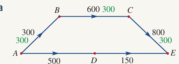
Solution part (c): Adding a new road
A new road is being built from town D to town C with a capacity of cars per hour. This creates an additional path: A→D→C→E.
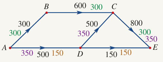
For the new path A→D→C→E:
- A to D: cars per hour
- D to C: cars per hour (new road)
- C to E: cars per hour
The smallest capacity on this path is cars per hour, but we need to be careful. Since we're already using cars per hour on road C→E through the first path, the actual capacity through C to E decreases.
Looking at the diagram more carefully, the new path has a maximum flow of cars per hour after accounting for shared roads.
The new overall maximum flow is:
Total cars per hour
Answer: After the new road is built, the maximum traffic flow from A to E increases to 800 cars per hour.
Cuts in network flow
For complex networks with many vertices and edges, calculating maximum flow by examining every possible path becomes difficult. A more efficient method uses the concept of cuts.
What is a cut?
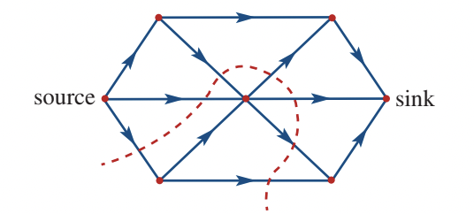
A cut is an imaginary line drawn across a directed graph that completely separates the source from the sink. You can think of a cut as an imaginary barrier that completely blocks all flow through the network.
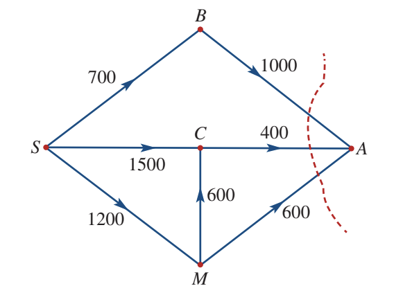
In the diagram above, the red dashed line represents a cut. This cut divides the network into two regions.
Valid cuts vs invalid cuts
A line across a network is only a valid cut if it completely separates the source from the sink.
Example of a valid cut:
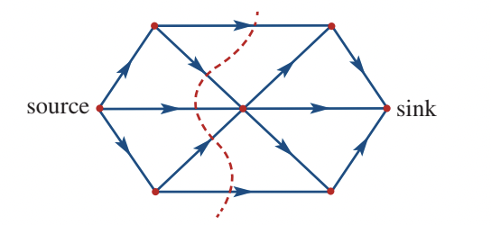
This dotted line is a valid cut because all pathways from source to sink are blocked. No material can flow from the source to the sink.
Example of an invalid cut:
This dotted line is not a valid cut because material can still flow from the source to the sink through pathways that aren't blocked. Not all routes have been cut.
Calculating cut capacity
The cut capacity is the sum of the capacities of all edges that cross the cut from the source side to the sink side.
Critical Rule for Cut Capacity:
Only count an edge's capacity if the flow direction is from the source side to the sink side of the cut. Edges flowing in the opposite direction (from sink side to source side) are not included in the cut capacity.
Think of a cut as taking a snapshot of all the flow crossing from one side to the other at that point in the network.
Key points about cuts
- A cut is an imaginary line that completely separates source from sink
- Cut capacity equals the sum of capacities of edges crossing from source side to sink side
- Direction matters - only count edges flowing source→sink across the cut
- A cut represents the maximum possible flow that could pass through that cross-section of the network
Maximum-flow minimum-cut theorem
One of the most important principles in network flow analysis is the maximum-flow minimum-cut theorem.
The theorem
Maximum-Flow Minimum-Cut Theorem:
The flow through a network cannot exceed the capacity of any cut in the network. Furthermore, the maximum flow through the network equals the capacity of the minimum cut.
In simpler terms:
- The actual flow can never be greater than any cut's capacity
- The maximum possible flow equals the smallest (minimum) cut capacity in the network
This theorem provides a powerful shortcut: instead of checking every possible path through a complex network, we can find the minimum cut and immediately know the maximum flow.
Worked example: Calculating cut capacity
Worked Example: Determining Cut Capacities
Problem
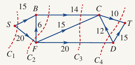
Calculate the capacity of the four cuts (C₁, C₂, C₃, and C₄) shown in the network below. The source is vertex S and the sink is vertex T.
Solution
Cut C₁:
Cut C₁ passes through two edges:
- S to B: capacity
- S to F: capacity
Both edges flow from source side to sink side, so both are counted.
Capacity of C₁
Cut C₂:
Cut C₂ passes through three edges:
- B to C: capacity
- F to B: capacity (flows from sink side to source side - not counted)
- S to F: capacity
Only the edges flowing from source side to sink side are counted.
Capacity of C₂
Cut C₃:
Cut C₃ passes through three edges:
- B to C: capacity
- B to D: capacity
- F to D: capacity
All edges flow from source side to sink side.
Capacity of C₃
Cut C₄:
Cut C₄ passes through three edges:
- D to T: capacity
- D to C: capacity (flows from sink side to source side - not counted)
- C to T: capacity
Only count edges flowing from source side to sink side.
Capacity of C₄
Summary: The minimum cut is C₄ with a capacity of 30. According to the maximum-flow minimum-cut theorem, the maximum flow through this network is 30.
Worked example: Finding maximum flow using cuts
Worked Example: Maximum Flow Using the Theorem
Problem
The table below shows the flow capacities (FC) of edges in a network. Determine the maximum flow from S to T.
| From | To | FC | From | To | FC |
|---|---|---|---|---|---|
| S | A | 8 | B | T | 5 |
| S | C | 11 | C | B | 3 |
| A | T | 3 | C | T | 1 |
| B | A | 5 |
Solution
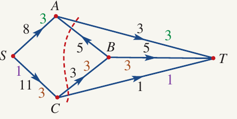
Step 1: Construct the network diagram
Using the table data, we draw the directed graph with vertices S, A, B, C, and T. Each edge is labelled with its capacity.
Step 2: Identify possible paths
We can identify several paths from S to T:
- Path 1 (green): S→A→T with capacities and . Minimum capacity
- Path 2 (brown): S→C→B→A→T. This path can carry units
- Path 3 (purple): S→C→T with capacities and . Minimum capacity
Step 3: Find the minimum cut
Looking at the network, we can identify a cut (shown by the red dotted line) that separates S from T. This cut passes through:
- A to T: capacity
- B to T: capacity (but limited by incoming flow)
- C to T: capacity
Considering the actual flow constraints and the paths identified, the minimum cut capacity is:
Minimum cut capacity
Step 4: Calculate maximum flow
According to the maximum-flow minimum-cut theorem, the maximum flow equals the minimum cut capacity.
Maximum flow
We can verify this by adding the flows through different paths:
- Path 1 contributes: units
- Path 2 contributes: units
- Path 3 contributes: unit
Total flow ✓
Answer: The maximum flow from S to T is 7 units.
Verification Tip: The maximum flow must always equal the minimum cut capacity. If these values don't match, check your calculations for errors in either the path analysis or cut capacity calculation.
Remember!
Key Points to Remember:
-
Network flow problems model the movement of materials from a source to a sink through a network of connections with limited capacities.
-
The maximum flow through any path is determined by the smallest capacity edge along that path (the bottleneck principle).
-
A cut is an imaginary line that completely separates the source from the sink. The cut capacity is the sum of capacities of edges crossing from the source side to the sink side only.
-
The maximum-flow minimum-cut theorem states that the maximum flow through a network equals the capacity of the minimum cut. This provides a shortcut for finding maximum flow in complex networks.
-
When calculating cut capacity, only count edges that flow from the source side to the sink side of the cut. Edges flowing in the opposite direction are excluded.