Diffraction Patterns and Interference (HSC SSCE Physics): Revision Notes
Diffraction Patterns and Interference
Introduction to light as a wave
In the early 19th century, experiments provided strong evidence that light behaves as a wave. The classical wave model, combined with electromagnetic field theory developed by Faraday and Maxwell, successfully explains many behaviours of light. Light is modelled as an electromagnetic wave that reflects, refracts, diffracts, and creates interference patterns, just like mechanical waves such as sound.
Light exhibits four key wave behaviours that demonstrate its wave nature:
- Reflection - bouncing off surfaces
- Refraction - bending when passing between different media
- Diffraction - spreading around obstacles
- Interference - combining to create patterns of constructive and destructive regions
Young's double-slit experiment
Historical background
Thomas Young was a remarkable scientist born in 1773. He was extraordinarily gifted, teaching himself to read by age two and learning Latin by age six. At twenty-one, he was elected to the Royal Society. His interests spanned Egyptology, pure science, and medicine.
When Young read Newton's Opticks at seventeen, he was initially impressed with Newton's corpuscular theory (the idea that light consists of particles). However, by 1800, Young identified problems with this particle model:
- At certain boundaries, such as between water and air, some light was refracted while some was reflected. Particle behaviour could not easily explain this dual behaviour.
- The corpuscular theory failed to explain why different colours of light refract by different amounts.
Young knew that sound behaved as a compression wave, and that interference between two waves of different frequencies created beats. This knowledge from acoustics led him to design his famous double-slit experiment, which would ultimately demonstrate the wave nature of light.
The double-slit experiment explained
In the double-slit experiment, light passes through two narrow, closely spaced slits. The resulting interference pattern appears on a distant screen. This pattern arises because light waves from the two slits travel different distances to reach any given point on the screen.
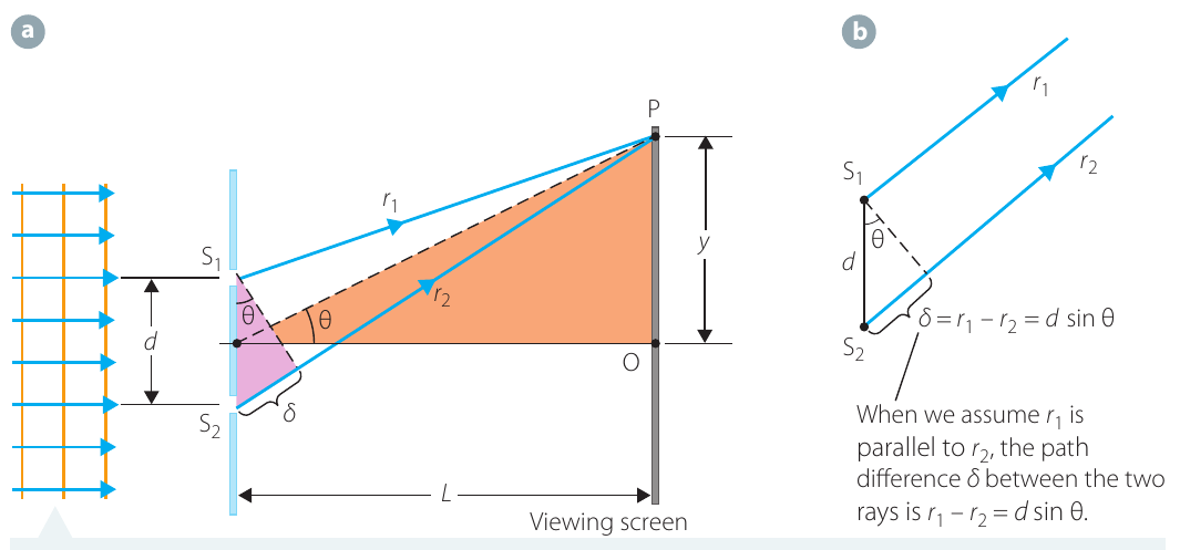
The key concept is path difference - the difference in distance travelled by light from each slit to a point on the screen.
Understanding path difference
The path difference is given by:
where and are the distances from each slit to a point on the screen.
When the screen is far from the slits, the two rays are approximately parallel. This allows us to express the path difference in terms of an angle :
where is the separation between the slits.
Conditions for interference
Understanding Constructive and Destructive Interference:
Constructive interference (bright spots or antinodes) occurs when waves arrive in phase - when peaks align with peaks. This happens when the path difference equals a whole number of wavelengths:
Destructive interference (dark spots or nodes) occurs when waves arrive out of phase - when peaks meet troughs. This happens when the path difference is a half-integer number of wavelengths:
The integer is called the order number and counts the fringes from the central maximum.
Position of bright and dark spots
For small angles (when ), we can relate the angle to the vertical position on the screen:
where is the distance from the slits to the screen.
The positions of bright spots are:
The positions of dark spots are:
Notice that the positions of both bright and dark spots depend on:
- The wavelength - longer wavelengths create wider spacing
- The slit separation - closer slits create wider spacing
- The distance to the screen - greater distances create wider spacing
Determining wavelength
By measuring the distance between successive bright spots and knowing the slit separation, we can determine the wavelength:
Conversely, if we know the wavelength, we can calculate the slit separation. This makes Young's double-slit experiment a powerful tool for measuring wavelengths.
Single-slit diffraction
Fraunhofer diffraction
When light passes through a slit with finite width (not infinitesimally narrow), an interference pattern forms based on the width of the slit itself. This phenomenon is called Fraunhofer diffraction.
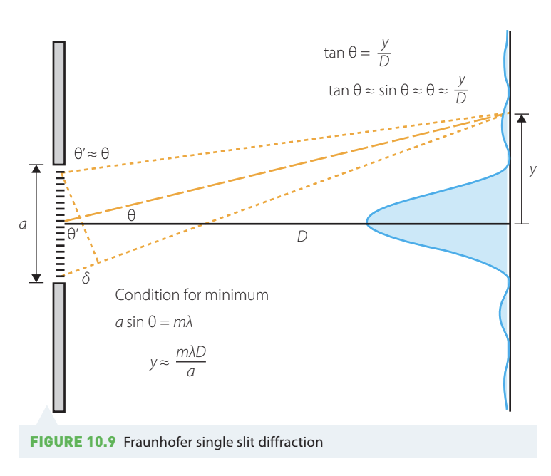
Huygens' Principle and Single-Slit Diffraction:
According to Huygens' principle, every point along the slit acts as a source of waves. These waves interfere with each other, creating a distinctive pattern. The pattern differs from double-slit interference, with a large central bright region and smaller secondary peaks.
Conditions for single-slit minima
To understand single-slit diffraction, imagine dividing the slit into two halves. The first minimum (dark spot) occurs when each ray from the first half cancels with a corresponding ray from the second half.
Single-Slit Minima Condition:
The condition for minima is:
where is the slit width.
Note that is not included because corresponds to the central maximum, not a minimum.
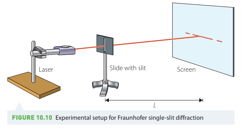
Investigation 10.2: Single-slit diffraction
Aim: To observe the behaviour of light incident on a single slit.
Materials:
- Red laser pointer
- Laser mount
- Prepared slides with single slits of different widths
- Slide mount (boss head and clamp)
- Projection screen
- Metre ruler
Safety considerations:
| What are the risks? | How can you manage these risks? |
|---|---|
| Temporary disturbance to vision from laser | Take strict precautions when using the laser. Do not point it at anybody. Do not look directly at the beam. Take particular care that all eyes are well out of the path of any reflections from the back of the slide. |
Method:
- Arrange the laser, a single-slit slide, and the screen as shown in the diagram.
- Measure the distance from the slide to the screen.
- Turn on the laser and observe the pattern formed on the screen.
- Repeat for each of the other slides with different slit widths.
Results: Sketch each pattern observed. Note the relative brightness of the various spots.
Discussion: Consider how wave theory explains the observed patterns.
What to Observe:
As you change the slit width, you should notice that:
- Narrower slits produce wider diffraction patterns
- Wider slits produce narrower diffraction patterns
- The central maximum is always the brightest feature
- Secondary maxima become progressively dimmer
This inverse relationship between slit width and pattern width is a characteristic feature of diffraction.
Combined double-slit and single-slit effects
In real double-slit experiments, the pattern combines contributions from both the slit width (Fraunhofer diffraction) and the separation between slits (double-slit interference). The overall pattern shows a diffraction envelope (determined by slit width) with interference substructure (determined by slit separation).
Number of interference fringes
We can calculate how many interference fringes appear within the central diffraction maximum.
For double-slit interference maxima:
For single-slit minimum: (when )
When the first single-slit minimum coincides with a double-slit maximum:
Calculating the Number of Visible Fringes:
The total number of visible fringes is:
This accounts for fringes on both sides of the central maximum, plus the central fringe itself. For example, if , then fringes are visible within the central diffraction envelope.
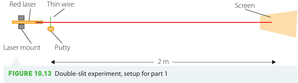
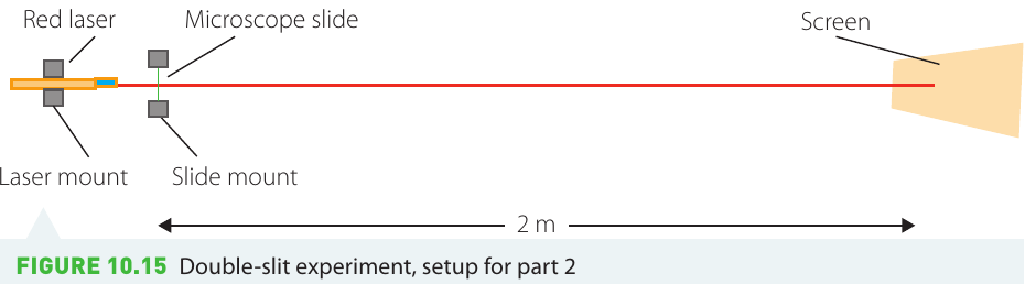
Investigation 10.3: Double-slit diffraction
This investigation has two parts.
Aim: To determine the distance between two slits on a microscope slide using double-slit diffraction.
Part 1: Determine the wavelength of the laser
Materials:
- Red laser pointer and laser mount
- Putty
- m thin, flexible wire
- Thin dowel rod
- Projection screen
- Metre ruler
- Wire cutters
Safety considerations:
| What are the risks? | How can you manage these risks? |
|---|---|
| Temporary disturbance to vision from laser | Take strict precautions when using the laser. Do not point it at anybody. Do not look directly at the beam. |
| Cuts from razor blades | Carefully tape the blades together. When marking the slide, handle the blades via the clip. |
| Burns from candle flame | Waft the slide carefully through the yellow flame. |
Method:
- Place a small lump of putty on the bench about m from the screen.
- Cut about cm off the thin flexible wire. Mount this vertically, protruding upwards from the putty.
- Mount the laser so it points directly towards the mounted wire and the screen beyond.
- Turn on the laser. This generates a diffraction pattern on the screen (a series of bright red dots).
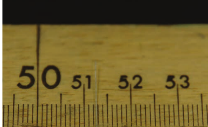
- Measure from the leftmost visible dot to the rightmost visible dot with the metre ruler.
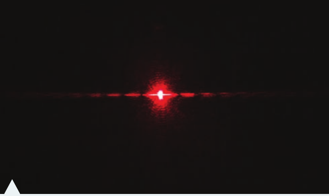
- Determine and record the average separation between dots (measure from centre to centre).
- Wind the remaining wire onto the dowel rod, counting the number of windings carefully, until you have covered about cm of the dowel. Keep windings tight with no spacings or overlap.
- Measure the distance from the first winding to the last along the dowel as precisely as possible.
- Divide the measured distance by the number of windings to determine the thickness of the wire.
Results: Using the antinode separation distance and the thickness of the wire, calculate the wavelength of the laser using .
Discussion: Red laser pointers typically produce wavelengths between 630 and 650 nm. Compare your calculated value to this expected range.
Experimental Tips for Accurate Results:
- Make your measurements as precise as possible by measuring multiple fringe separations and dividing by the number
- Count the wire windings carefully - errors here will affect your final wavelength calculation
- Ensure the wire is wound tightly with no gaps or overlaps
- Keep the laser beam perpendicular to the wire for the clearest diffraction pattern
Part 2: Determine the distance between slits
Method:
- Bind two razor blades together with sticky tape. Place them in a clip with a thin scrap of paper between them.
- Light a candle (or Bunsen burner on yellow safety flame).
- Carefully waft a microscope slide through the flame. The incomplete combustion produces carbon particles that coat the slide.
- Using the bound razor blades, gently make a double slit on the carbon-covered slide.
- Mount the slide with the slits vertical.
- Shine the laser through the double slit onto the screen m away.
- Determine and record the spacing between adjacent antinodes on the screen.
Results: Using the antinode separation distance and the calculated wavelength from Part 1, calculate the distance between the slits using .
Analysis:
- Determine the ratio of slit separation () to slit width ().
- Determine the slit width.
- Calculate how many interference fringes appear within the first diffraction maximum using where .
Creating Good Double Slits:
The key to this experiment is creating clean, parallel slits:
- Waft the slide quickly through the flame to get an even carbon coating
- Make one smooth, steady cut with the razor blades - don't go back and forth
- The paper spacer between the blades determines your slit separation
- If the pattern isn't clear, try making a fresh double slit on a different part of the slide
Diffraction gratings
How diffraction gratings work
Diffraction gratings function similarly to double-slit experiments, but with many parallel slits very close together. When planar light passes through, diffraction spreads the light across numerous grating lines, each generating interference.
The path difference between adjacent lines remains:
The condition for maxima (bright spots) is:
Why Diffraction Gratings Are Powerful:
The key advantage of diffraction gratings over simple double slits is the number of lines. While the location of maxima doesn't depend on the number of lines, having many lines produces:
- Much sharper, narrower peaks
- Better separation of different wavelengths
- Higher resolution for spectroscopy
- More precise measurements
Intensity patterns
The location of maxima does not depend on the number of grating lines, . However, the thickness of the maxima is inversely proportional to . More grating lines produce thinner, sharper maxima.
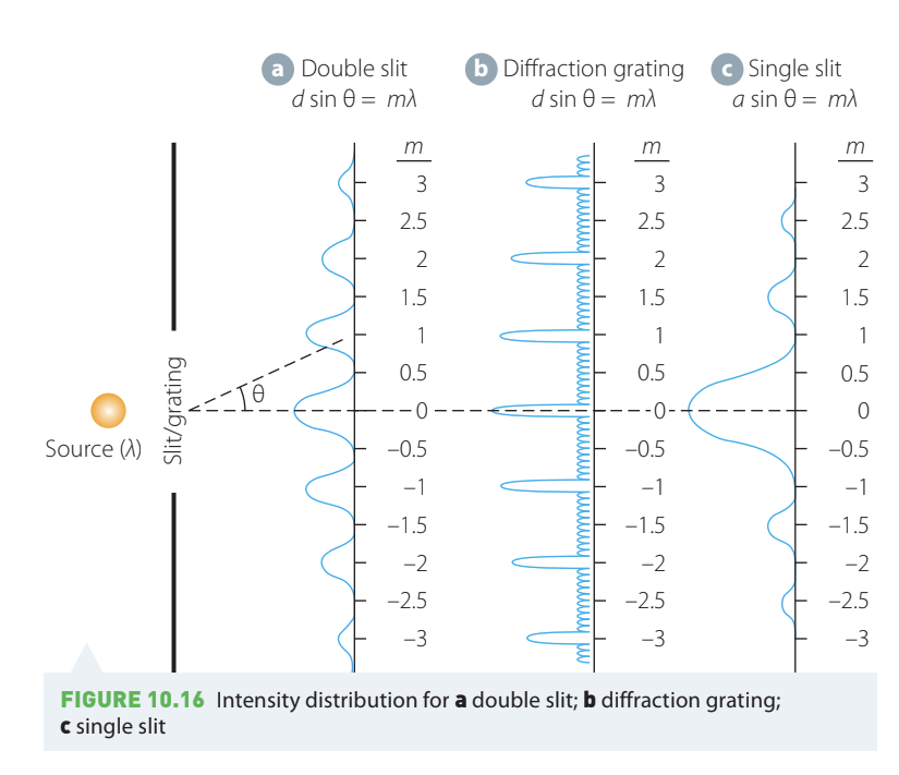
Sources with mixed wavelengths (such as incandescent light) generate separate peaks for each wavelength, creating a spectrum.
Investigation 10.1: Interference patterns with incandescent light
Aim: To observe interference patterns from an incandescent light source using a diffraction grating.
Materials:
- Incandescent light source (desk lamp)
- Magnifying lens
- Diffraction grating (CD or DVD disc)
- Mount for disc
- Screen (wall, whiteboard, or large sheet of paper)
Safety considerations:
| What are the risks? | How can you manage these risks? |
|---|---|
| Temporary disturbance to vision from magnified desk lamp | Do not look directly at the magnified light beam. Take care when reflecting the light beam off the diffraction grating that you do not stare directly at the undiffracted light. |
Method:
- Shine the incandescent light source through the magnifying glass so the beam focuses on the diffraction grating. Use the outer edge where the grooves are closest to parallel.
- Observe the light diffracted by the grating.
Results: Sketch your observations, noting carefully any colour sequences.
Discussion: Explain the pattern of colours in terms of light as a wave, noting what happens to different wavelengths.
What You Should See:
You should observe a spectrum of colors spreading out from the central bright spot. The order of colors should be:
- Red (longest wavelength) appears at the largest angles
- Orange, yellow, green, blue
- Violet (shortest wavelength) appears at the smallest angles
This happens because longer wavelengths diffract more than shorter wavelengths for the same order .
Investigation 10.4: Interference of monochromatic light
Aim: To observe interference of monochromatic light using a diffraction grating.
Materials:
- Red laser pointer and laser mount
- Diffraction grating (CD or DVD disc)
- Two-dimensional diffraction grating (nylon stocking)
- Diffraction grating mount
- Projection screen
- Metre ruler
Safety considerations:
| What are the risks? | How can you manage these risks? |
|---|---|
| Temporary disturbance to vision from laser | Take strict precautions when using the laser. Do not point it at anybody. Do not look directly at the beam. Take particular care that when the laser is diffracted off the grating, all eyes are well out of the path of any reflections. |
Method:
- Set the diffraction grating parallel to the floor about m from the projection screen.
- Shine the laser onto the CD diffraction grating so the beam is forward diffracted onto the projection screen. Use the outer edge where grooves are closest to parallel.
- Observe the light pattern diffracted off the grating.
- Measure the distances between spots on the screen.
- Replace the CD grating with the two-dimensional grating and repeat.
Results: Sketch the patterns observed in both cases, indicating distances between selected spots.
Analysis: Using the wavelength determined in Investigation 10.3, calculate the spacing of the gratings in each case using .
Two-Dimensional Gratings:
When you use the nylon stocking (a two-dimensional grating), you should observe a rectangular grid of spots rather than just a line. This occurs because the stocking has periodic structure in both horizontal and vertical directions, creating diffraction in two dimensions simultaneously.
Worked example: Calculating antinode separation
Worked Example: Calculating Antinode Separation
Question: A green laser has a wavelength of nm. When light from the laser passes through a slit of width mm and travels a distance m to the screen, what would be the separation of the antinodes on the screen?
| Answers | Logic |
|---|---|
| nm, m, mm | Identify relevant data in the question. |
| Choose the appropriate equation. | |
| Let | First bright spot. Subsequent bright spots will be at integral multiples of the value we obtain for . |
| Substitute values with correct units. | |
| m | Calculate the answer. |
| The antinodes are m apart. | State the final answer with correct units and appropriate significant figures. |
Practice problems:
A blue laser has a wavelength of nm. It passes through two parallel slits, each mm wide, separated by a distance of mm. The distance to the screen is m.
a) What would be the antinode separation caused by Fraunhofer diffraction? b) What would be the antinode separation caused by the double-slit interference?
Remember!
Key Points to Remember:
-
Path difference determines whether waves interfere constructively (bright spots) or destructively (dark spots).
-
Constructive interference occurs when the path difference equals whole wavelengths: .
-
Destructive interference occurs when the path difference equals half-integer wavelengths: .
-
Single-slit diffraction creates a pattern with a bright central maximum and smaller secondary maxima, with minima at .
-
Diffraction gratings with many slits produce sharp, well-defined maxima, making them useful for analysing light spectra.
-
The order number counts the fringes from the central maximum: is the central bright spot, are the successive orders.
-
For combined double-slit and single-slit effects, the number of visible fringes is where .