Modelling Resistance in Parallel Circuits (VCE SSCE Physics): Revision Notes
Modelling Resistance in Parallel Circuits
Introduction to parallel circuits
A parallel circuit contains junctions where the current from the power source divides before reaching different components. The current then rejoins the main circuit path and returns to the power source. This is fundamentally different from series circuits, where current flows through a single path.
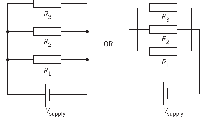
Both circuit diagrams shown above represent the same parallel configuration. Each resistor (, , and ) is connected directly across the power supply terminals, meaning each receives the full supply voltage.
Key characteristics of parallel circuits:
- Multiple paths exist for current to flow
- Each component can be controlled independently with separate switches
- Components continue to function even if others are switched off
- Each branch receives the same potential difference as the power supply
The key distinction between series and parallel circuits is in how current flows: series circuits have a single continuous path, while parallel circuits have multiple branching paths where current can split and recombine at junctions.
Voltage and current behaviour in parallel circuits
Potential difference
In a parallel circuit, the potential difference across each component is identical and equals the supply voltage:
This occurs because each component connects directly between the positive and negative terminals of the power source.
Think of parallel components as being "side by side" - each one experiences the full "push" (voltage) from the power supply, just like multiple doors in a building all open to the same street.
Current distribution
The total current leaving the power source splits at junctions according to the resistance in each branch. The sum of all branch currents equals the total current:
Components with lower resistance carry more current, while those with higher resistance carry less current. Using Ohm's law (), the current through each branch can be calculated.
Current in parallel circuits behaves like water flowing through multiple pipes - it naturally takes the path of least resistance, with more current flowing through branches with lower resistance.
Calculating equivalent resistance in parallel circuits
General formula for parallel resistance
When resistors are connected in parallel, we calculate the equivalent resistance using:
Where:
- is the equivalent resistance (Ω)
- are the individual resistances (Ω)
Simplified formula for two resistors
When only two resistors are in parallel, we can use this more convenient formula:
This "product over sum" formula can be applied repeatedly to solve circuits with three or more resistors: first combine two resistors, then use that result with the third resistor, and so on.
Critical Concept: The equivalent resistance of parallel resistors is always smaller than the smallest individual resistor. This occurs because adding parallel paths provides additional routes for current to flow, reducing the overall opposition to current.
This is the opposite of series circuits, where adding more resistors increases total resistance!
Special case: identical resistors
When identical resistors (each with resistance ) are connected in parallel:
For example, two identical resistors in parallel give an equivalent resistance of .
This special case formula makes quick calculations easy: four identical resistors in parallel give of equivalent resistance.
Worked example: calculating parallel resistance
Question: Calculate the equivalent resistance for these parallel circuits:
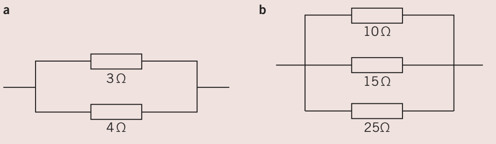
Worked Example: Solution for circuit (a)
Using the two-resistor formula with and :
Alternative method using the general formula:
Worked Example: Solution for circuit (b)
For three resistors (, , ):
Finding a common denominator (150):
Check: Notice that 4.84 Ω is less than the smallest individual resistor (10 Ω), confirming our understanding of parallel circuits.
Worked example: series-parallel combinations
Question: Calculate the total resistance of this combination circuit:
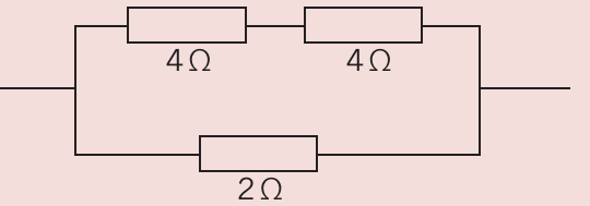
Worked Example: Combination Circuit Solution
Step 1: Identify the parallel section. The two resistors at the top are in series with each other:
Step 2: Now we have an resistor in parallel with a resistor:
Alternative calculation:
Graphical methods for circuit analysis
Series circuits: a graphical approach
For series circuits, we can use current-voltage (I-V) graphs to determine equivalent resistance. Consider two resistors ( and ) connected in series:
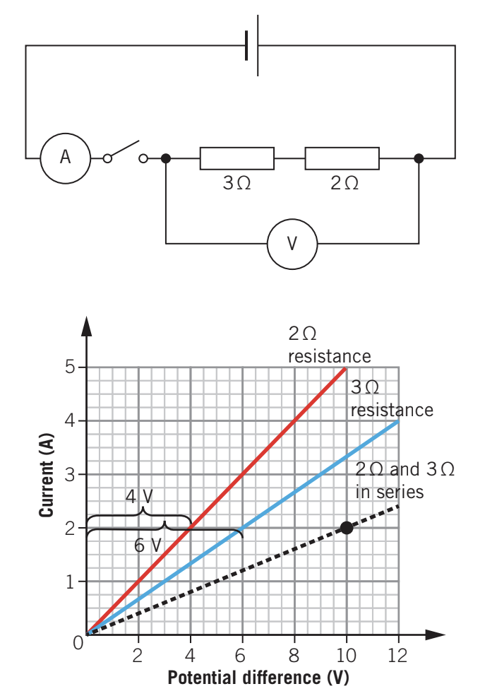
Method:
- Plot - lines for each individual resistor
- Choose a fixed current value (e.g., )
- Read the voltage across each resistor at this current ( and )
- Add these voltages to get the total voltage ()
- Plot the point (, ) for the combined resistance
- Repeat for other current values to construct the combined - line
The gradient of the combined line gives , which matches .
Key principle for series circuits: Current is constant, so we add voltages when constructing the combined graph.
Parallel circuits: a graphical approach
For parallel circuits, the analysis differs because voltage is constant while current varies:
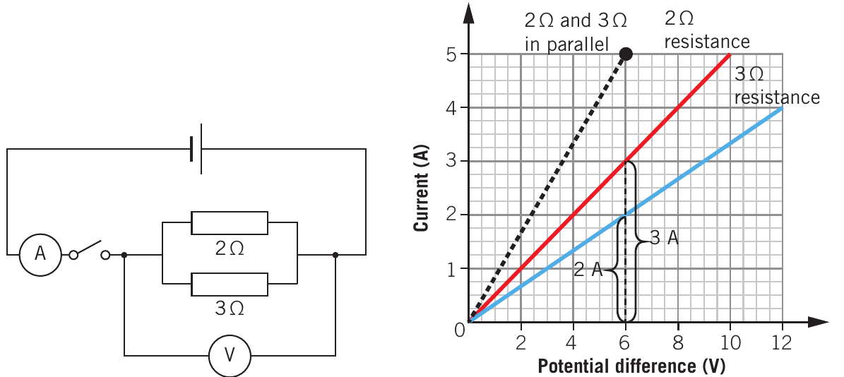
Method:
- Plot - lines for each individual resistor
- Choose a fixed voltage value (e.g., )
- Read the current through each resistor at this voltage ( and )
- Add these currents to get total current ()
- Plot the point (, ) for the combined resistance
- Repeat for other voltage values to construct the combined - line
The gradient gives , so .
Key principle for parallel circuits: Voltage is constant, so we add currents when constructing the combined graph.
Comparison of graphical methods:
- Series circuits: Combined line has smaller gradient (higher resistance) than individual components
- Parallel circuits: Combined line has steeper gradient (lower resistance) than individual components
Complex circuits with mixed connections
Real circuits often combine series and parallel sections. To analyse these:
- Identify all parallel combinations and calculate their equivalent resistances
- Redraw the circuit replacing parallel sections with single equivalent resistors
- Calculate series combinations
- Repeat until the circuit is simplified to a single equivalent resistance
The key to solving complex circuits is to work systematically - simplify one small section at a time, redrawing after each step to see the remaining circuit more clearly.
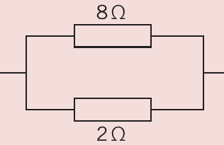
Example: three-resistor combination
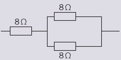
For an resistor in series with two parallel resistors:
Worked Example: Three-Resistor Combination
Step 1: Two identical resistors in parallel:
Step 2: Series combination:
Example: more complex reduction
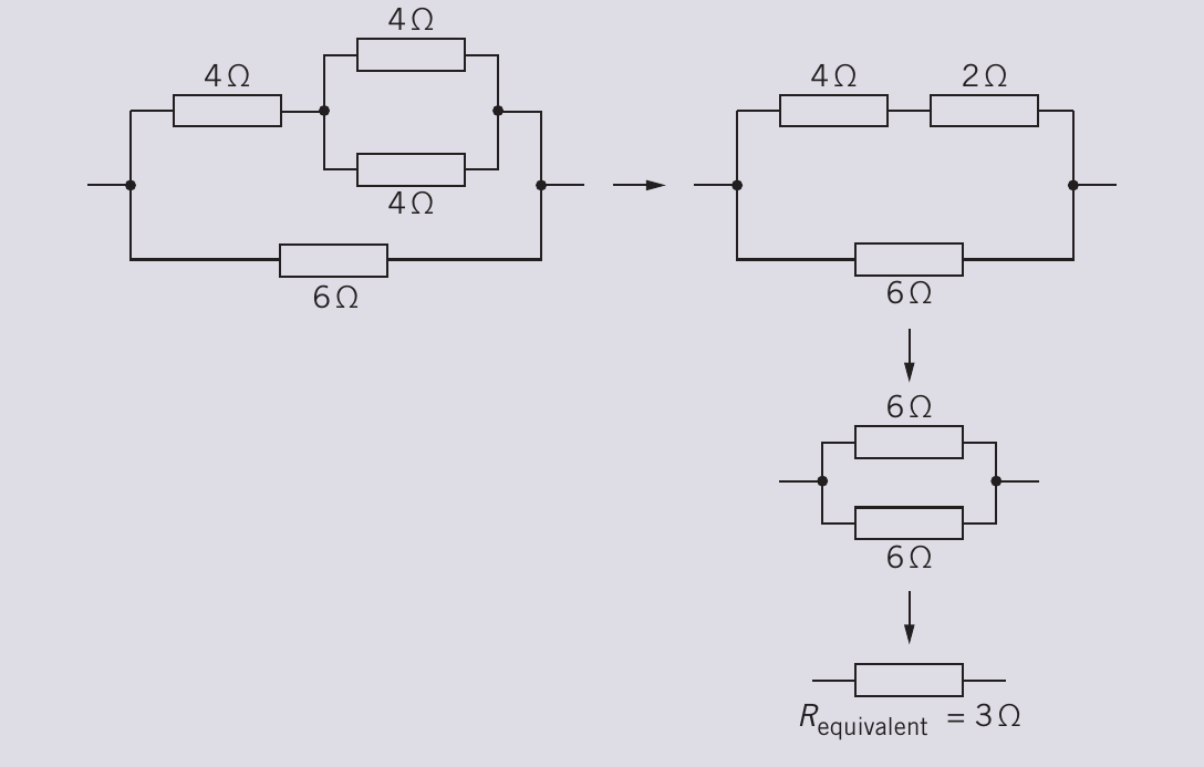
This circuit has , , and resistors. Working systematically:
Worked Example: Complex Circuit Reduction
Step 1: The two resistors on the right ( and ) are in parallel:
Step 2: This equivalent is in series with the resistor:
(Note: The actual calculation shown in the textbook yields for a different circuit configuration.)
Bridge circuits
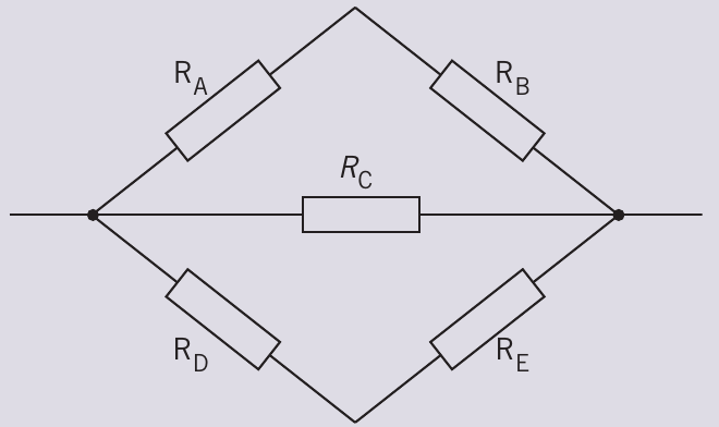
Some circuits form bridge configurations where resistors are arranged in a diamond pattern. These require careful analysis to identify which resistors are in series and which are in parallel.
For example, in this bridge circuit:
- and are in series
- and are in series
- These two series combinations are each in parallel with
The equivalent resistance is then:
Bridge circuits look more complicated than they are! The key is to trace the current paths carefully and identify which components truly share the same connection points (parallel) versus which form a chain (series).
Practical investigation: measuring parallel circuits
To verify parallel circuit behaviour experimentally:
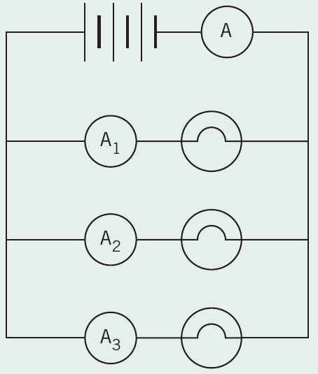
Apparatus needed:
- Power supply
- Three resistors (lamps)
- Four ammeters (labelled , , , )
- Voltmeter
- Connecting wires
Method:
- Connect three resistors in parallel as shown
- Place an ammeter in the main circuit before the junction ()
- Place an ammeter in each branch (, , )
- Use a voltmeter to measure potential difference across each resistor
Expected observations:
- Voltmeter readings across all three resistors are equal
- Sum of branch currents equals main current:
- Each resistor operates independently
Exam tip: When answering questions about parallel circuits, always check that the sum of branch currents equals the total current, and verify that all branch voltages equal the supply voltage. These are the defining characteristics of parallel circuits.
Problem-solving strategies
Identifying parallel vs series connections
Parallel connections:
- Components share the same two connection points
- Current has multiple paths to choose from
- Each component can be removed without breaking the circuit for others
Series connections:
- Components form a single chain
- Current has only one path
- Removing one component breaks the entire circuit
If you can trace a path from one component directly to another without passing through any junctions, they are likely in series. If current must split at a junction to reach different components, those components are in parallel.
Step-by-step approach to complex circuits
- Redraw if needed: Sketch the circuit in a clearer format if the original diagram is confusing
- Identify smallest combinations: Start with the simplest parallel or series groups
- Calculate step-by-step: Find equivalent resistance for each small group before moving to larger combinations
- Redraw after each step: Update your circuit diagram, replacing each calculated group with its equivalent resistance
- Check your answer: Ensure parallel combinations give smaller resistance and series combinations give larger resistance
Common pitfalls to avoid
Mistakes to watch out for:
-
Don't assume geometry: Resistors that look parallel on a diagram might not be electrically parallel. Check that they truly share the same connection points.
-
Check your arithmetic: The reciprocal calculations for parallel circuits are easy to get wrong. Always verify by checking units and magnitudes.
-
Remember the difference: In series, voltages add (current constant). In parallel, currents add (voltage constant). Don't mix these up!
-
Verify your result: For parallel circuits, the equivalent resistance must be less than the smallest individual resistor. If it's not, check your calculation.
Remember!
Key Points to Remember:
-
Parallel circuits have multiple current paths with junctions where current divides and rejoins
-
Voltage is the same across all components in a parallel section, equal to the supply voltage
-
Total current equals the sum of individual branch currents:
-
Equivalent resistance formula:
-
Parallel resistance is always smaller than the smallest individual resistor (more paths = less resistance)
-
Graphical method for parallel: Fix voltage, add currents to find points on the combined - graph
-
Complex circuits: Simplify parallel sections first, then combine series resistances step by step