Modelling Resistance in Series Circuits (VCE SSCE Physics): Revision Notes
Modelling Resistance in Series Circuits
Introduction to electrical resistance in transport
Electric vehicles (EVs) are becoming increasingly important in reducing carbon emissions from transport. EVs use regenerative braking systems that convert kinetic energy back into electrical energy stored in batteries, making them more efficient than traditional vehicles. Understanding how electrical circuits work, including resistance and series circuits, is essential for designing and operating these systems.
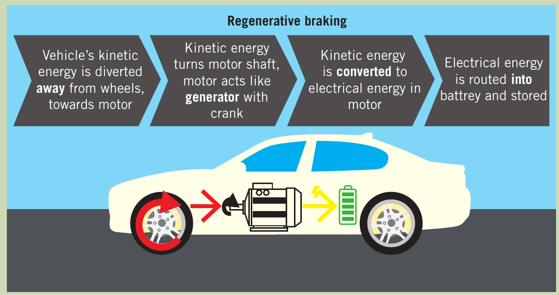
Regenerative braking captures energy that would normally be lost as heat during braking. While it doesn't fully return all expended energy, it significantly increases an EV's overall range compared to vehicles with conventional braking systems.
What is electrical resistance?
Understanding resistance through circuits
When electrical energy is supplied to a circuit, the relationship between current, potential difference, and energy can be simple or complex depending on the components involved.
Resistance is a measure of how much an object or material impedes the flow of current. It is measured in units called ohms (symbol: ).
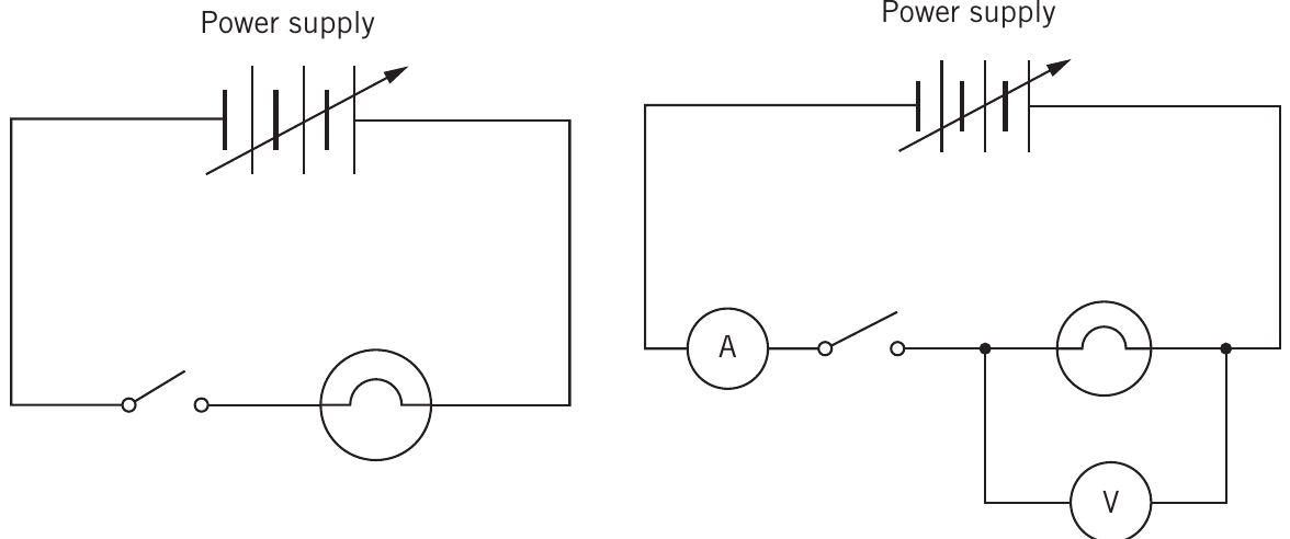
To investigate resistance, we connect a circuit with:
- A variable voltage power supply
- An ammeter (to measure current) connected in series
- A voltmeter (to measure potential difference) connected in parallel
- The component being tested (e.g., a light bulb or resistor)
Current-voltage (I-V) graphs
The relationship between current and potential difference can be shown using I-V graphs (current versus potential difference graphs).
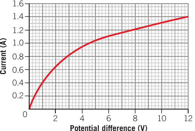
For a light bulb, the I-V graph is curved (non-linear). This shows that resistance is not constant. As current increases, the filament gets hotter, and hotter metals become more resistant to current flow. Think of thermally vibrating metal ions getting in the way of drifting electrons, like rugby players trying to dodge through a moving defence.
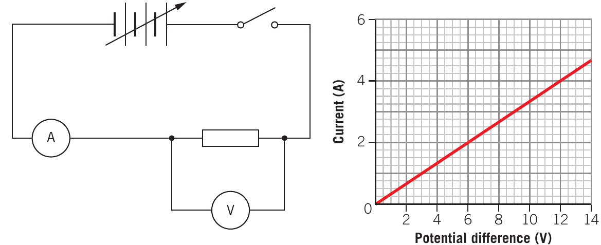
For a laboratory resistor kept at low temperature, the I-V graph is a straight line through the origin. This shows that current increases steadily as potential difference increases. The resistance remains constant.
Ohmic and non-ohmic resistors
Ohmic resistor: A material that gives a straight-line I-V graph. The ratio of potential difference to current remains constant. Such resistors are said to "obey Ohm's law."
Non-ohmic resistor: A material where the resistance changes with current or temperature, producing a curved I-V graph (like the light bulb).
Ohm's law
Ohm's law states that for certain materials (ohmic conductors), the potential difference across a conductor is directly proportional to the current through it.
Formula
or rearranged:
Where:
- = Potential difference (volts, V)
- = Current (amperes, A)
- = Resistance (ohms, )
Key points about Ohm's law
Key Points About Ohm's Law:
- For an ohmic resistor, is constant at a given temperature
- The ratio can be calculated from the gradient of an I-V graph: or
- For a non-ohmic device like a light bulb, resistance changes with current and temperature
Worked example: Car headlight resistance
Worked Example: Car Headlight Resistance
A car LED headlight is powered by a 12.0 V battery. When operating normally, there is a current of 5.0 A through it. Find the resistance.
Solution:
Using Ohm's law:
Given: V, A
Rearranging for resistance:
The resistance of the headlight is 2.4 Ω.
In practice, when current is large enough to cause heating, the resistance may increase. The ratio gives the resistance at any moment, but depending on the component, resistance may not be constant (non-ohmic).
Worked example: Current in a light bulb
Worked Example: Current in a Light Bulb
An old-fashioned incandescent light bulb has a resistance of 960 when connected to the 230 V mains power supply. What current does it draw?
Solution:
Using Ohm's law:
Given: V,
Rearranging for current:
The light bulb draws a current of 0.24 A.
Important note about meters
Critical Meter Characteristics:
Ammeters are designed to have the lowest possible resistance (ideally zero) so they don't significantly alter the circuit they're measuring. They have negligible potential difference across them.
Voltmeters are designed to have very high resistance (ideally infinite, typically in megaohms, ) so they take very little current from the circuit.
For this course, all meters are considered to be ideal.
Series circuits
What is a series circuit?
A series circuit is when circuit components are connected one after the other in a continuous loop, so that the same current passes through each component. There is only one path for current to flow.
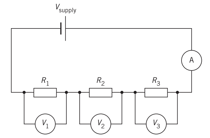
Properties of series circuits
In a series circuit, there are three fundamental properties that govern how current, voltage, and resistance behave:
Property 1: Current is the same through all components
- Electrons do not stop anywhere on their way around the circuit
- If you measure current at any point, you get the same value
Property 2: Potential differences add up to equal the supply voltage
- Each resistor gets a share of the total voltage proportional to its resistance
- The greater the resistance, the greater its share of potential difference
Property 3: Resistances add up to give the total equivalent resistance
- This allows us to calculate the total resistance of multiple resistors connected in series
Equivalent resistance in series
Equivalent resistance is the value of a single resistor that could replace a number of individual resistors to give the same effect in the circuit.
For resistors connected in series:
Where:
- = Total equivalent resistance for resistors in series ()
- = Resistance of each resistor ()
Deriving the series resistance formula
Using Ohm's law for each resistor:
For each component:
Since and the current is the same through all:
Worked example: Series resistance calculation
Worked Example: Series Resistance Calculation
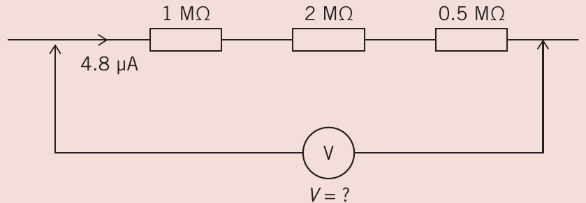
Three resistors of 1 M, 2 M and 0.5 M are connected in series and carry a current of 4.8 A. Find the potential difference across the combination.
Solution:
Step 1: Calculate equivalent resistance
Step 2: Apply Ohm's law to find total potential difference
The potential difference across the series combination is 16.8 V.
Worked example: Meter readings in a circuit
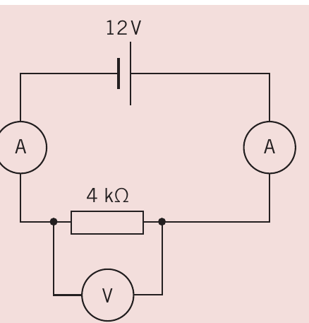
Worked Example: Meter Readings in a Circuit
What would each of the meters read in this circuit with a 12 V supply and a 4 k resistor?
Solution:
For a circuit with a single resistor, the entire potential difference from the battery is dissipated in the resistor.
Voltmeter reading: The voltmeter will read 12 V.
Ammeter readings: Using Ohm's law to find current:
Since it's a series circuit, both ammeters will read 3 mA.
Potential (voltage) dividers
What is a potential divider?
A potential divider (or voltage divider) is a series circuit with two or more components where the voltage is shared (or divided) between the components in proportion to their resistances.
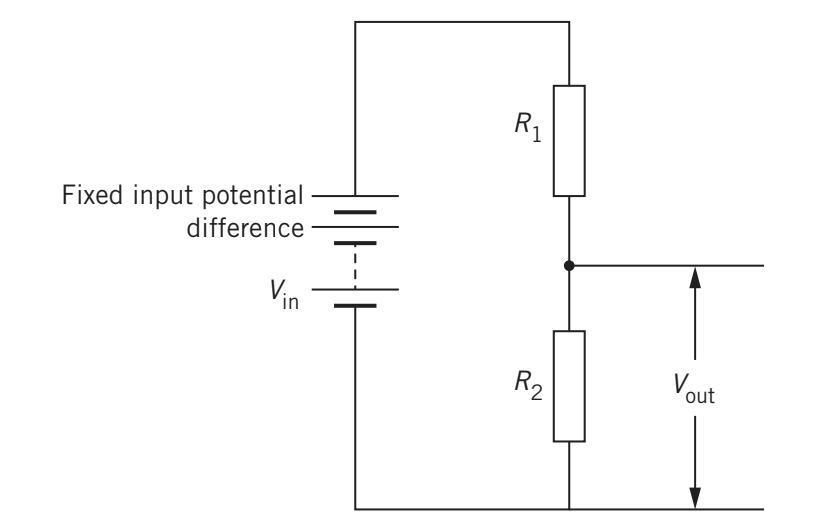
A simple potential divider consists of two resistors in series. The output potential difference is taken from the point between the two resistors. By varying the values of each resistor, any output voltage can be obtained from a fixed input voltage.
How potential dividers work
In the circuit shown:
- Input voltage:
- Two resistors in series: (top) and (bottom)
- Output voltage: (measured across )
The current through both resistors is:
The output voltage across is:
Substituting the expression for current:
Potential divider formula
or equivalently:
Where:
- = Input potential difference (V)
- = Output potential difference across (V)
- = Resistances of the resistors ()
Understanding the ratio
The ratio makes sense because in a series circuit, the potential drop across each component depends on its resistance. The potential drop across will be the same proportion of as is of the total resistance.
Applications of potential dividers
Potential dividers are useful because:
- They can reduce a fixed voltage to any required lower voltage
- Using variable resistors, the output voltage can be adjusted
- Using temperature-sensitive resistors (thermistors), they can control heating systems
- Using light-dependent resistors (LDRs), they can control streetlights
Worked example: Mobile phone charging
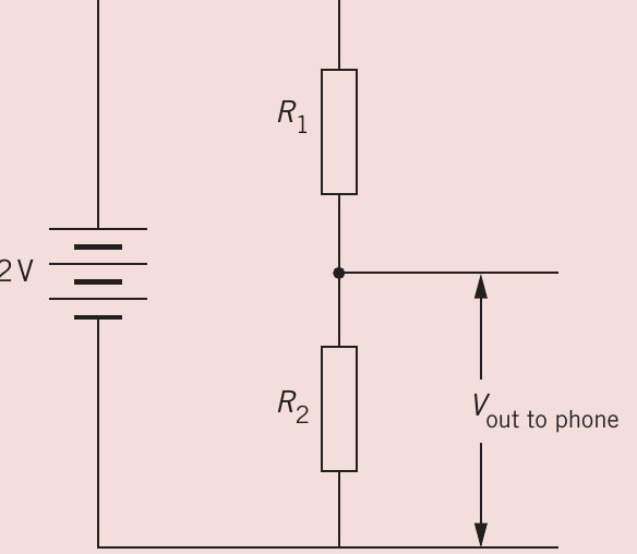
Worked Example: Mobile Phone Charging
A mobile phone requires a potential difference of up to 5 V to charge correctly. The only power supply available is a 12 V battery. Available resistors are 0.8 k, 1.0 k, 1.2 k, and 1.4 k. Design a potential divider to supply the required 5 V.
Solution:
Since 5 V is less than half of 12 V, place the smaller resistor as (at the output) so the larger resistor can be (at the top). Let's try k.
Using the potential divider formula:
Since :
Answer: Use the 1.4 kΩ resistor as and the 1.0 kΩ resistor as .
Safety Considerations Before Implementation:
- Can the battery supply enough current without overheating?
- Can the resistors and wires handle the current safely?
- Would the battery supply more current than the phone can handle?
More detailed understanding is needed before experimenting with expensive equipment.
Example calculations with potential dividers
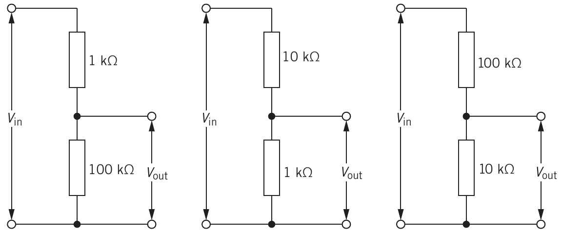
For three different potential divider configurations with V:
Configuration 1 (Left circuit): k, k
Configuration 2 (Middle circuit): k, k
Configuration 3 (Right circuit): k, k
Key limitation: The output voltage can never be larger than the input voltage in a potential divider. The ratio is always less than 1.
Resistor colour code
Why use colour codes?
Many electrical components are very small, making it difficult to print values in words or numbers. The international resistor colour code provides a standardized way to indicate resistance values and tolerances.
How the colour code works
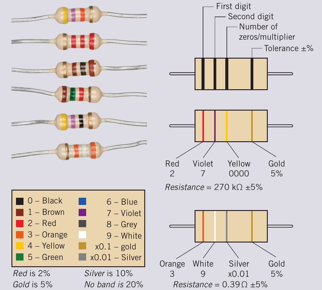
Fixed resistors use coloured bands to indicate:
- First band: First digit
- Second band: Second digit
- Third band: Number of zeros (power of ten multiplier)
- Fourth band (if present): Tolerance (measurement accuracy)
Colour-to-number key
Resistor Colour Code Reference Table
| Colour | Digit | Multiplier | Tolerance |
|---|---|---|---|
| Black | 0 | - | |
| Brown | 1 | - | |
| Red | 2 | 2% | |
| Orange | 3 | - | |
| Yellow | 4 | - | |
| Green | 5 | - | |
| Blue | 6 | - | |
| Violet | 7 | - | |
| Grey | 8 | - | |
| White | 9 | - | |
| Gold | - | 5% | |
| Silver | - | 10% | |
| No band | - | - | 20% |
Examples
Example 1: Red-Violet-Yellow-Gold
- First digit: Red = 2
- Second digit: Violet = 7
- Multiplier: Yellow = 0000 ()
- Tolerance: Gold = ±5%
- Value: 270,000 Ω = 270 kΩ ±5%
Example 2: Orange-White-Silver-Gold
- First digit: Orange = 3
- Second digit: White = 9
- Multiplier: Silver =
- Tolerance: Gold = ±5%
- Value: 39 × 0.01 = 0.39 Ω ±5%
Tolerance ranges
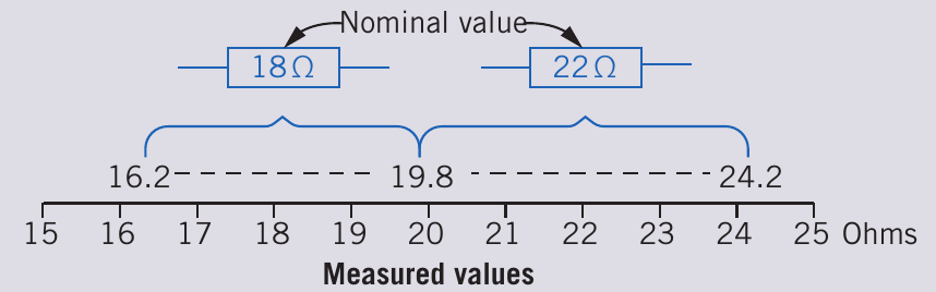
A resistor rated at 18 ±10% can have a measured value from 16.2 to 19.8 Ω.
A resistor rated at 22 ±10% can have a measured value from 19.8 to 24.2 Ω.
These two resistors together cover the range from 16.2 to 24.2 with no gaps, demonstrating how the standard values are designed to provide complete coverage across resistance ranges.
Standard resistor values
Standard resistors are produced in values based on non-overlapping tolerances. For 20% tolerance, a typical series is:
10, 12, 15, 18, 22, 27, 33, 39, 47, 56, 68, 82 (then repeated with different multipliers)
The third band (multiplier) can change to give any power of ten within the range produced.
Key formulas summary
Essential Formulas and Units
| Quantity | Symbol | Unit |
|---|---|---|
| Potential difference | Volt (V) | |
| Current | Ampere (A) | |
| Resistance | Ohm () |
Ohm's law:
Series resistance:
Potential divider:
Remember!
Key Points to Remember:
- Resistance measures how much a component opposes current flow, measured in ohms ()
- Ohmic resistors have constant resistance and produce straight-line I-V graphs; non-ohmic resistors have variable resistance and produce curved I-V graphs
- In series circuits, current is the same through all components, and resistances add up:
- Potential dividers split voltage proportionally based on resistance values, following:
- The resistor colour code uses coloured bands to indicate resistance value and tolerance, enabling quick identification without measurement