MOSFET (metal-oxide semiconducting field-effect transistor) (AQA A-Level Physics): Revision Notes
13.1.1 MOSFET (metal-oxide semiconducting field-effect transistor)
Overview
A MOSFET (Metal-Oxide-Semiconductor Field-Effect Transistor) is a type of switch used in electronics that can control the flow of current and voltage without any moving parts. It is highly efficient, versatile, and widely used in various circuits to manage power, acting as both a switch and an amplifier.
Understanding Semiconductors:
To comprehend MOSFETs, it's essential to understand the properties of semiconductors. Semiconductors allow limited movement of charge carriers (electrons and holes) only if enough energy is provided. Here's how different materials compare:
- Conductors: No additional energy is required for charge movement.
- Insulators: A large amount of energy is needed for charge movement.
- Semiconductors: A small amount of energy is enough to move charges through the material.
Charge Carriers in Semiconductors:
- Electrons: Removed from atoms using thermal energy.
- Holes: Formed when an electron leaves an atom, effectively acting like a positively charged particle that "moves" as electrons jump into these vacancies.
Types of Semiconductors:
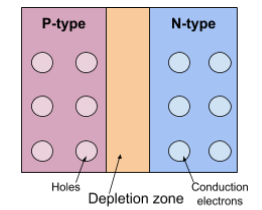
- N-type: Has an excess of conduction electrons.
- P-type: Has an excess of holes (positive charge carriers). When N-type and P-type materials are brought close together, a depletion zone forms at the junction. This zone acts as an insulator, preventing charge carriers from moving across unless a sufficient external voltage is applied.
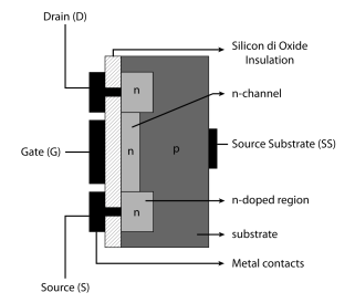
Structure of a MOSFET:
A MOSFET has three main terminals:
- Drain (D): Where electrons leave, connected to the positive terminal.
- Gate (G): Controls the switching action, turning the MOSFET on/off.
- Source (S): Supplies electrons, connected to the negative terminal. In a circuit, the current flows from the Drain to the Source in the form of conventional current (positive to negative).
Operation of MOSFETs:
A MOSFET uses two p-n junctions. When no voltage is applied to the Gate, a depletion zone blocks the current flow. However, applying a positive voltage to the Gate induces an electric field, which reduces the depletion zone, enabling current flow from Source to Drain. Key operating modes include:
- Cut-off Region:
- Gate voltage is below the threshold, so the MOSFET is off and acts as an open switch.
- Ohmic (Linear) Region:
- Acts as a variable resistor, current increases with .
- Saturation Region:
- MOSFET is fully on, current depends on rather than .
- Breakdown Region:
- High causes excessive current, potentially damaging the MOSFET.
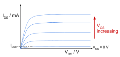
Parameters to Know:
- : Voltage between Drain and Source.
- : Voltage between Gate and Source.
- : Threshold voltage needed to form a conducting channel.
- : Small current flowing even when is zero.
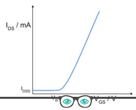
Graph Characteristics:
A graph of (Drain-Source current) vs reveals how the MOSFET behaves as changes. Initially, rises slowly; as increases past , rises sharply, indicating the channel's increasing conductance.
Using MOSFETs as Switches:
- Off state: , no current flows.
- On state: , maximum current flows (saturated). Protection for Inductive Components: When using MOSFETs with inductive loads, such as coils, connect a protection diode across the component. This diode prevents back-emf (from Lenz's Law) from damaging the MOSFET.
Important Note:
Due to high input resistance, MOSFETs can accumulate electrostatic charge on the Gate. To avoid damage, a resistor can be placed between Gate and ground to discharge any excess charge.