Analogue and digital signals (AQA A-Level Physics): Revision Notes
13.2.1 Difference between analogue and digital signals
Analogue Signals
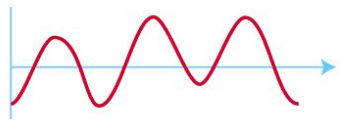
Analogue signals are continuous, meaning they can take any value within a range. They are typically used to represent quantities from the "real world," such as:
- Light intensity (e.g., through LDRs and photodiodes)
- Sound (e.g., through microphones)
- Magnetic field strength (e.g., Hall effect sensors)
- Temperature (e.g., thermistors)
- pH levels (e.g., pH probes)
- Oxygen levels (e.g., lambda sensors)
- Pressure (e.g., flow sensors) A visual representation shows analogue signals as smooth and continuous waveforms.
Digital Signals
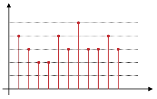
Digital signals are discrete and can only take on one of two values, often represented as or (binary). This binary system corresponds to "off" () and "on" () states, which are essential for digital circuits and computing.
- In digital circuits, the off state typically equals 0V, while the on state is often 5V.
- Digital signals are represented using binary numbers (base-) to encode information, where each binary digit (bit) holds a value of or . A byte is a group of 8 bits, often representing a larger numerical value.
| 2^7$$(128) | |||||||
|---|---|---|---|---|---|---|---|
| 1 | 0 | 0 | 0 | 0 |
Example Conversion:
The binary number 10001101 (base-) converts to 141 in decimal (base-) by calculating:
| Decimal Number (Base-) | Binary Number (Base-) | |---|---|---|---| | 0 | 0000 | | 1 | 0001 | | 2 | 0010 | | 3 | 0011 | | 4 | 0100 | | 5 | 0101 | | 6 | 0110 | | 7 | 0111 | | 8 | 1000 | | 9 | 1001 | | 10 | 1010 |
Conversion from Analogue to Digital
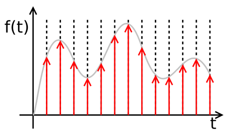
For analogue signals to be processed by computers, they are often converted into digital format using an Analogue-to-Digital Converter (ADC). This involves:
- Sampling the analogue signal at regular intervals (determined by the sampling rate).
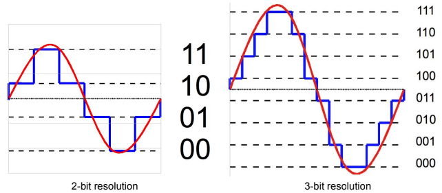
- Quantisation, where each sample's amplitude is rounded to the nearest available digital value.
- Encoding each quantised value as a binary number, resulting in a sequence of numbers that represents the signal over time.
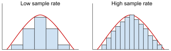
The sampling rate affects the quality of the conversion. A higher sampling rate captures more detail but requires more data.
Key Concepts in Digital Sampling
- Sampling Rate: The number of samples taken per second. A higher rate improves quality by capturing more signal details.
- The minimum sampling rate should be twice the highest frequency in the analogue signal to accurately represent it (Nyquist rate).
- Resolution: The smallest change in an analogue signal that can be represented in digital form.
- Resolution increases with the number of bits used for each sample.
- For example, a -bit ADC has possible values, allowing finer detail in representation.
Advantages of Digital Signals
- Easier to process: Digital data is straightforward for computers and electronic systems to handle.
- Less affected by noise: Digital signals can maintain quality over long distances.
- Encodable and secure: Signals can be encoded for security or data integrity.
- Efficient transmission: Digital signals are compatible with fibre optics, enabling fast and reliable data transmission.
Disadvantages of Digital Signals
- Loss of exactness: Due to quantisation, digital signals may not represent continuous variations as accurately as analogue signals.
- Complex transmission: Digital systems often require higher bandwidth and more sophisticated infrastructure than analogue systems.
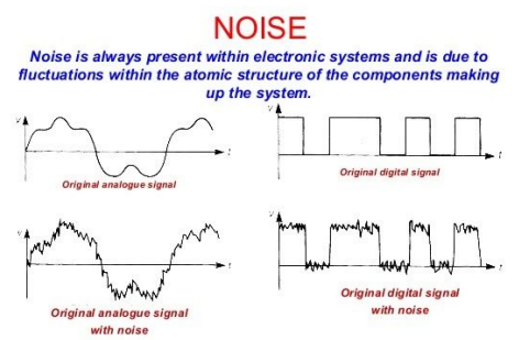
Noise in Analogue vs. Digital Signals
- Analogue signals are more affected by noise, as noise changes the shape of the waveform directly.
- Digital signals are less affected, as noise typically needs to be very strong to alter the distinct "on" and "off" states.
Methods to Combat Noise
- Repeaters: Amplify signals to reduce attenuation (loss of strength), though they may amplify noise too.

- Regenerators: Clean up signals by switching on only at certain voltage levels, effectively filtering out weaker noise.

Pulse Code Modulation (PCM)
PCM is a method of converting an analogue signal to digital, involving:
- Sampling: Recording the signal's amplitude at set intervals.
- Quantisation: Rounding each sample to the nearest available digital value.
Quantisation and Encoding
- Quantisation: During the ADC process, the continuous values of the analogue signal are assigned discrete values by rounding. This introduces an approximation error, as the original signal cannot be perfectly represented in digital form.
- Encoding: Once quantised, these discrete values are converted into binary numbers. The length of the binary number (or bit length depends on the resolution of the ADC. Higher resolution means more bits, allowing for a more accurate digital representation of the original signal.
Data Output and Transmission
- Parallel Output: ADCs generally produce a parallel output, meaning that all bits representing each sample are output simultaneously. This can be efficient within certain electronic systems but is less suitable for long-distance transmission.
- Serial Transmission: For digital data transmission, especially over long distances or single-channel paths, parallel data needs to be converted to serial data. This is achieved by using a parallel-to-serial converter, which rearranges the data into a single stream. Serial transmission sends one bit after another in sequence, forming a single data stream.
Using a parallel-to-serial converter allows digital data, initially in a parallel format, to be transmitted over a single line, which is more efficient for many digital communication systems, especially in the context of pulse code modulation (PCM).