Sequential logic (AQA A-Level Physics): Revision Notes
📚 Revision Notes
13.5.2 Sequential logic
infoNote
Sequential logic circuits differ from the previously studied combinational logic circuits because they produce outputs that depend not only on current inputs but also on past inputs. This time-dependent response results in outputs that follow a specific sequence, useful in timing, counting, and sequencing applications.
Key Components of Sequential Logic
Binary Counters:
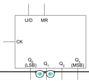
- Binary Counters are circuits that count pulses in binary, typically controlled by a clock signal. A basic 4-bit binary counter has the following inputs and outputs:
- CK (Clock Input): This is where the clock pulses enter the circuit. Each pulse increments the counter.
- U/D (Up/Down Control): Determines counting direction. If the signal is 1, the counter counts up; if it's 0, it counts down.
- MR (Master Reset): Resets all counter outputs to 0 when triggered by a signal of 1.
- Outputs (Q₀ to Q₃): The counter's binary output, where Q₀ is the Least Significant Bit (LSB) and Q₃ is the Most Significant Bit (MSB).
Counter Operation and Timing:
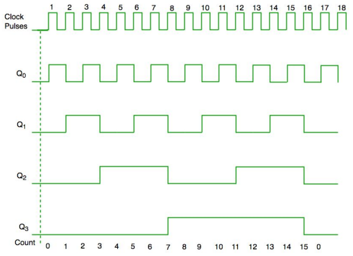
- Each output in the counter changes state based on clock pulses, with Q₀ changing every pulse, Q₁ every second pulse, and so on, making Q₃ the slowest-changing bit. This characteristic allows the counter to act as a frequency divider.
- A timing diagram visualises the behaviour of each bit (Q₀ to Q₃) in response to clock pulses, showing how binary values increase or decrease over time.
Counting Cycle and Resetting:
- The counter continues to count up to for an n-bit counter, resetting to zero after reaching the maximum count. For a 4-bit counter, it will count from 0 to 15 (binary 0000 to 1111) and then reset.
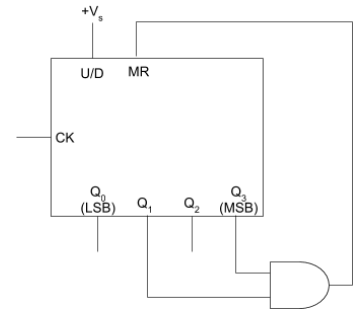
Modulo Counters:
- Modulo-N Counters reset at any chosen number, not just powers of two. For instance, a modulo-10 counter (also known as a BCD counter) will reset after reaching 9. This can be achieved by connecting logic gates to control the master reset based on a desired output.
- Example: A BCD Counter (Binary-Coded Decimal Counter) resets after reaching decimal 9, making it useful in digital displays that show values from 0 to 9.
Johnson (Decade) Counter:
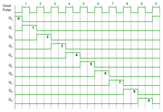
- A Johnson Counter (or Decade Counter) cycles through a sequence of 10 states, with outputs turning on and off in sequence. Unlike binary counters, its outputs do not represent binary values but rather a sequence pattern. This type of counter has applications in timing circuits.
- The timing diagram for a Johnson counter shows the unique sequence of states over several clock pulses.
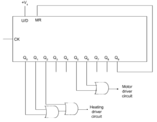
Sequencing Applications:
- Johnson Counters and other sequential logic counters are often used in systems that require operations in a specific order or timing, such as heating elements or motors controlled on specific time cycles.
- Example Application: A sequencing circuit might control a heating element for 3 seconds, wait 2 seconds, then activate a motor for 2 seconds in a repeating 10-second cycle.
Important Notes
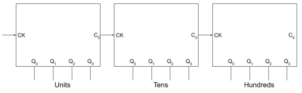
- Carry Out (Cₒ): Many counters have a carry-out feature that allows the output to act as a clock signal for another counter. This lets multiple counters connect in series to count higher values.
- Rising-Edge Triggering: These counters respond to the rising edge (from 0 to 1) of the clock pulse. Sequential logic circuits are essential in applications requiring time-based operations, from digital clocks to complex programmable systems, and provide foundational understanding for more advanced digital electronics.