Astables (AQA A-Level Physics): Revision Notes
13.5.3 Astables
Astable Circuits Overview
Astables are a type of oscillating circuit that generates continuous pulses of a fixed frequency and duration. These circuits are often referred to as pulse generators because they produce clock pulses in a repeating sequence. An astable circuit has no stable states, meaning it constantly switches between "on" and "off" states with a consistent period. This property is crucial in applications requiring repetitive timing, such as clocks or signal timers.
Understanding the Period of Oscillation ( :
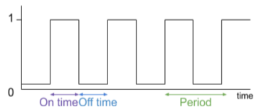
The period is defined as the time taken for one complete cycle of the waveform — from the start of one pulse to the start of the next. It includes:
- On Time ( - Duration when the output is in the "high" () state.
- Off Time - Duration when the output is in the "low" () state. The period can be calculated as:
Clock Rate (Pulse Frequency):
The clock rate (or pulse frequency) represents the number of pulses generated per second. This frequency is the reciprocal of the period:
Pulse Width and Duty Cycle:
- Pulse Width is the time duration that the pulse remains in its "on" state.
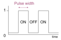
- Duty Cycle is a percentage measure of how long the pulse stays "on" in one cycle, calculated as:
For example, if and are equal, the duty cycle would be 50%.
Mark-to-Space Ratio:
The mark-to-space ratio defines the relationship between the duration of the "on" (mark) period and the "off" (space) period:
If , then this ratio is 1:1.
Astable Circuit Construction and Functioning
Astables are typically formed using an RC (Resistor-Capacitor) network connected to a NOT gate with hysteresis. This configuration allows the circuit to have two distinct switching thresholds (upper and lower), enabling the circuit to oscillate.
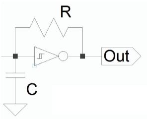
The operation of the circuit is as follows:
- Initially, the capacitor is uncharged. This causes the NOT gate output to be high (), and the capacitor begins to charge through the resistor.
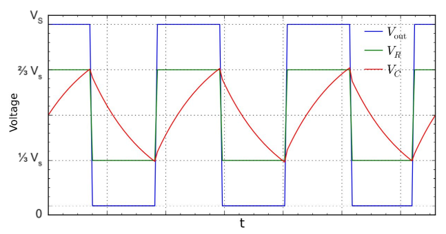
- When the voltage across the capacitor reaches the upper switching threshold, the NOT gate flips, causing its output to go low ().
- The capacitor then discharges through the resistor until the voltage reaches the lower switching threshold, triggering the NOT gate to flip back to high, and the cycle repeats. This oscillation creates a continuous output pulse, as shown in the voltage vs time graph.
Thresholds in the NOT Gate:
- Upper Threshold: Triggered at approximately .
- Lower Threshold: Triggered at around .
Calculating the Period and Pulse Frequency
For an RC astable circuit, the on time is the time for the capacitor to charge from to . The off time is the time for the capacitor to discharge back down to . Since the charging and discharging times are symmetrical:
Thus, the period is given by:
Finally, the pulse frequency is the reciprocal of the period: