Flow Problems (VCE SSCE General Mathematics): Revision Notes
Flow Problems
Introduction to directed graphs
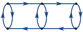
In graph theory, we use directed graphs (also called digraphs) to represent networks where the direction of connections matters. A directed graph uses arrows on the edges to show which way flow or movement can occur. When we add numerical information to these graphs, such as distances, times, or capacities, we call them networks.
Think of a road system around a city. The vertices represent intersections, and the edges represent roads connecting them. The arrows show which roads are one-way and which allow traffic in both directions.
Key terms you need to know:
- Vertices: Points or nodes in the network (like towns or intersections)
- Edges: Connections between vertices (like roads or pipes)
- Weights: Numbers labelling the edges (like distance or capacity)
- Network: A graph with numerical information on the edges
Understanding flow in networks
Flow problems involve the transfer of material from one point to another. This could be water flowing through pipes, traffic moving along roads, or data travelling through a network. Every flow problem has two key components:
- Source: The starting point where flow begins
- Sink: The destination where flow ends
The basic flow pattern is: source → flow through network → sink
In a flow network, the capacity of an edge represents the maximum amount that can flow through it in a given time. For example, a pipe might have a capacity of litres per minute, or a road might accommodate cars per hour.
Maximum flow in pipes connected in series
Let's explore what happens when pipes of different sizes connect together. Understanding this simple case will help you tackle more complex networks later.
Consider two pipes joining together to carry water from a source to a sink:
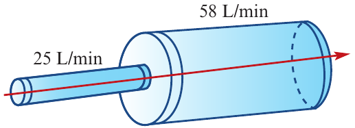
Even though the large pipe can handle litres per minute, the small pipe only allows litres per minute to pass through. The large pipe will never operate at its full capacity - it will only carry litres per minute. The flow through the entire system is restricted by the smallest pipe.
What happens if we reverse the connection?
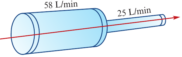
Now the large pipe delivers litres per minute to the junction, but the small pipe can only accept litres per minute. This creates a bottleneck - water backs up at the junction because the small pipe cannot handle all the water the large pipe delivers.
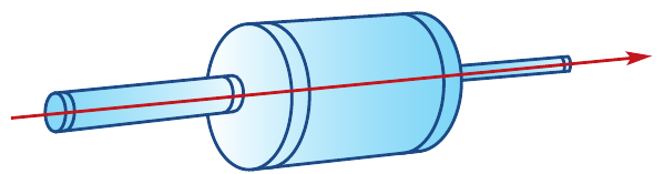
In both situations, the maximum flow through the complete pipe system equals litres per minute - the capacity of the smallest pipe in the connection.
Maximum flow rule for pipes in series:
When pipes of different capacities connect one after another, the maximum flow through the pipes equals the minimum capacity of the individual pipes.
This is called the bottleneck principle - the narrowest section determines the maximum flow through the entire system.
Calculating maximum flow by observation
For simple networks, we can find the maximum flow by examining different routes from source to sink and identifying the smallest capacity along each route.
Worked Example: Traffic flow network
Question: The network below shows roads connecting towns. Vertices , , , , and represent towns. The edges represent one-way roads, and the weights show the maximum number of cars that can travel on each road per hour.
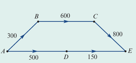
Part a: Find the maximum traffic flow from to through town .
Solution:
First, identify the route through town :
Looking at this route, the capacities are:
- to : cars per hour
- to : cars per hour
- to : cars per hour
The smallest capacity along this route is 300 cars per hour (the road from to ).
Therefore, the maximum flow from to through town is 300 cars per hour.
Part b: Find the maximum traffic flow from to overall.
Solution:
There are two possible routes from to :
Route 1 (through ): with maximum flow cars per hour
Route 2 (through ): with capacities and
The minimum capacity on route 2 is cars per hour.
Since these routes are independent, we add the maximum flows:
Part c: A new road is built from to with capacity cars per hour. Find the new maximum traffic flow from to .
Solution:
With the new road, we need to reconsider the flow distribution.
- Route through : can still carry cars per hour
- But now we also have: with capacity cars per hour
This means could receive: (from ) (from ) cars per hour
Since the road from to has capacity cars per hour, it can handle all this flow.
The new maximum flow is 800 cars per hour.
Cuts in flow networks
For networks with many vertices and edges, finding maximum flow by observation becomes difficult. We use a systematic method called cuts to solve these problems.
What is a cut?
A cut is an imaginary line across a directed graph that completely separates the source from the sink. Think of it as an imaginary barrier that completely blocks the flow through the network.
For a cut to be valid, it must satisfy one key requirement: no material can flow from the source to the sink after the cut is made. All pathways from source to sink must be blocked.
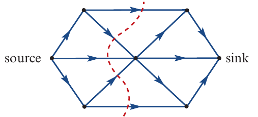
Valid cut: This cut completely separates source from sink. No flow can pass.
Invalid cut: This cut does not separate source from sink completely. Flow can still reach the sink through uncut paths.
Calculating cut capacity
The cut capacity is calculated by adding the capacities of all edges that cross the cut line. However, there's an important rule: only count edges that flow from the source side to the sink side of the cut.
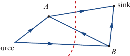
Why this direction rule? An edge flowing from the sink side back to the source side doesn't contribute to the flow reaching the sink, so it doesn't restrict the maximum flow.
Example of directional counting:
In this simple network, the cut passes through three edges:
The edge from to flows from the sink side to the source side, so it is NOT counted in the cut capacity calculation.
Worked Example: Calculating cut capacity
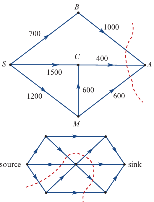
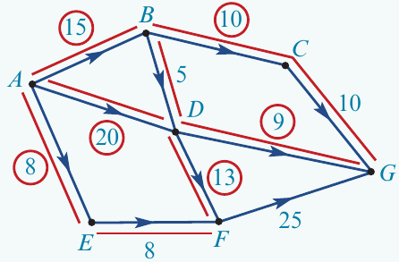
Question: Calculate the capacity of the four cuts shown in the network below. The source is vertex and the sink is vertex .
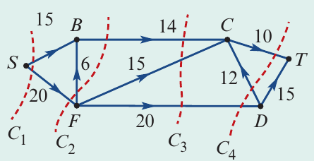
Solution:
Cut : All edges in flow from source to sink.
Cut : Note that the edge from to is not counted because it flows from sink side to source side.
Cut : All edges in flow from source to sink.
Cut : The edge from to flows from sink side to source side, so it is not counted.
Maximum-flow minimum-cut theorem
The capacity of a cut helps us determine the maximum flow through any network. Here's the key insight: the smallest cut capacity (minimum cut) equals the maximum flow possible through the network.
The maximum-flow minimum-cut theorem states:
The minimum cut capacity possible for a graph equals the maximum flow through the graph.
This theorem gives us a systematic method for finding maximum flow:
- Identify all possible cuts in the network
- Calculate the capacity of each cut
- Find the minimum cut capacity
- The minimum cut capacity equals the maximum flow
Using cuts to find maximum flow
Worked Example: Finding maximum flow using cuts
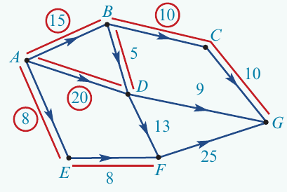
Question: Determine the maximum flow from to for the network shown below.
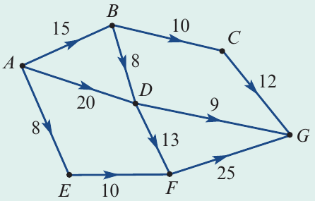
Solution:
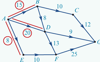
Step 1: Mark all possible cuts on the network.
Step 2: Calculate the capacity of each cut.
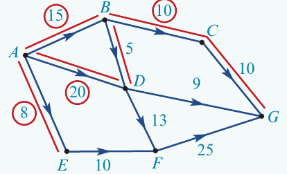
Step 3: Identify the minimum cut capacity.
The minimum cut capacity is 7 (from cut ).
Therefore, the maximum flow from to is 7.
Exam tip: When identifying cuts, be systematic. Start with cuts close to the source, then move progressively toward the sink. This helps ensure you don't miss any possible cuts.
Advanced method: Tracking flow through networks (optional)
An alternative method for finding maximum flow involves tracking the actual flow through every edge in the network. This method helps verify your answer and understand how flow distributes through the network.
How the tracking method works
The tracking method follows these steps:
- Start at the source and assume all edges leaving the source flow at maximum capacity
- Follow the flow through the network, vertex by vertex
- At each vertex, determine how the incoming flow distributes to outgoing edges
- If an edge cannot achieve its maximum capacity due to limited incoming flow, record the actual flow
- Continue until you reach the sink
- Sum all flow arriving at the sink to find the maximum flow
Worked Example: Tracking flow through a network
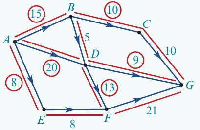
Question: The network below represents walking tracks through a koala sanctuary. Each edge shows the maximum number of people permitted on that track per hour. Find the maximum flow of people through the sanctuary from to .
Solution:
Starting at vertex (the source), three edges leave with capacities , , and . We assume these all flow at maximum capacity initially.
At vertex , we receive people per hour from . This flow splits:
- people per hour to (maximum capacity of that edge)
- people per hour to (only remain, even though the edge can handle )
At vertex , we receive people per hour from . The edge to has capacity , but only can flow through it.
At vertex , we receive:
- from
- from
- Total: people per hour
This flow of distributes:
- to (maximum capacity)
- to (maximum capacity)
- Note: , but we have available... Let me recalculate
Actually, from :
- to (capacity )
- to (capacity )
- Total out: ... This doesn't work with in.
Looking at the diagram more carefully from the source material, at vertex we receive:
- from
- from
- Total: people per hour
The edge from to has capacity , but only can flow.
Finally, at vertex (the sink), we receive:
- from
- from
- from
Multiple source and sink networks (optional)
Some networks have multiple entry points (sources) or exit points (sinks). For these networks, we need to consider each sink separately.
Calculating maximum flow with multiple sources and sinks
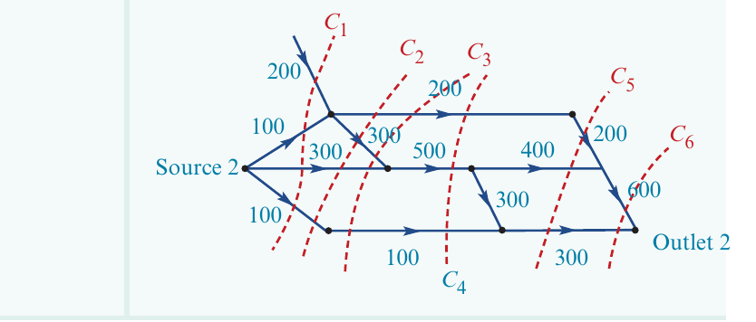
Worked Example: Multiple outlets
Question: Water enters a pipe network at Source 1 or Source 2 and exits at Outlet 1 or Outlet 2. The numbers represent maximum flow rates in kilolitres per minute. Find the maximum rate at which water can flow into the ocean at each outlet.
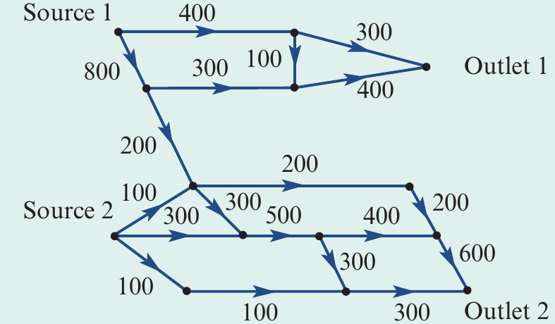
Solution:
We must consider each outlet separately because the maximum flow to one outlet may affect flow to the other.
For Outlet 1:
We identify all possible cuts that prevent water reaching Outlet 1. Note that the pipe leading to Outlet 2 never contributes to flow reaching Outlet 1.
The minimum cut capacity for Outlet 1 is 700 kilolitres per minute.
For Outlet 2:
For Outlet 2, we must include the pipe with capacity leading toward it in our cut calculations, as this pipe delivers water to Outlet 2.
The minimum cut capacity for Outlet 2 is 700 kilolitres per minute.
Important note: Although we found maximum flow of kilolitres per minute for each outlet, we cannot necessarily achieve both maximum flows simultaneously. The total maximum flow through the system may be less than kilolitres per minute due to shared pipes creating bottlenecks.
Remember!
Key Points to Remember:
- Directed graphs use arrows to show the direction of flow through a network
- Maximum flow in series: When pipes connect one after another, the smallest capacity determines maximum flow (bottleneck principle)
- A cut is an imaginary line that completely separates the source from the sink in a network
- Cut capacity equals the sum of capacities of edges crossing the cut from source side to sink side only
- Maximum-flow minimum-cut theorem: The minimum cut capacity in a network equals the maximum flow through that network - this is your most powerful tool for solving flow problems