Network Flows 1 (AQA A-Level Further Maths): Revision Notes
Network Flows 1
Introduction to network flows
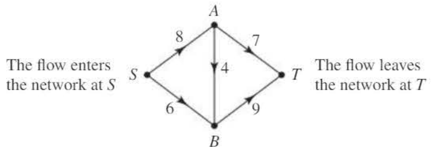
A directed network can be used to model routes through which commodities flow. These commodities could be electricity, oil, freight, data, or many other things that need to be transported from one location to another.
In a capacitated network, each arc has a capacity—this represents the maximum possible flow that can pass along that arc. The capacity acts as an upper limit on how much of the commodity can travel through that particular route.
Key terminology
Source (S): A node where flow enters the network. At the source, all arcs are directed away from the node—the flow originates here and moves outward into the network.
Sink (T): A node where flow leaves the network. At the sink, all arcs are directed towards the node—the flow terminates here after travelling through the network.
Flow in the arc: A non-negative number assigned to each arc representing the actual amount of commodity flowing along that arc.
Flow in the network: The complete collection of flows assigned to all arcs in the network.
Flow conditions
When a commodity flows through a network, the flow must satisfy certain fundamental conditions to be valid.
The feasibility condition
The feasibility condition states that the flow in an arc cannot be greater than its capacity.
In mathematical terms: For any arc, flow ≤ capacity
This makes intuitive sense—you cannot push more through a pipe than its maximum capacity allows. The capacity sets an upper bound on the flow.
The conservation condition
The conservation condition states that, at every node apart from S and T, the total inflow must equal the total outflow.
In other words: Total flow entering a node = Total flow leaving a node (for all nodes except the source and sink)
This reflects the fact that commodities cannot be stored at intermediate nodes—whatever flows in must flow out. There is no accumulation or loss of flow at these points.
The value of the flow
From the conservation condition, we can deduce an important result:
Total outflow from S = Total inflow to T
This value is called the value of the flow. It represents the total amount of commodity successfully transported through the entire network from source to sink.
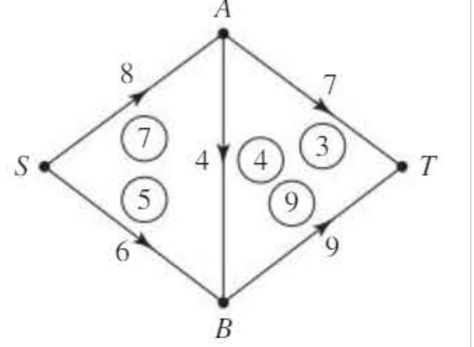
In the diagram above, a feasible flow is shown with the actual flow values circled on each arc. Notice how:
- At node A: inflow = 7, outflow = 7 ✓
- At node B: inflow = 9, outflow = 9 ✓
- Total outflow from S = 7 + 5 = 12
- Total inflow to T = 3 + 9 = 12 ✓
- Value of the flow = 12
Saturated and unsaturated arcs
When analysing flows in networks, we classify arcs based on whether they are operating at full capacity.
Saturated arc: An arc where the flow equals the capacity (flow = capacity). The arc is "full" and cannot carry any additional flow.
Unsaturated arc: An arc where the flow is less than the capacity (flow < capacity). The arc has spare capacity and could potentially carry more flow.
In the example above, arcs where flow = capacity (such as arc AB and BT with flow = capacity = 9) are saturated. The other arcs are unsaturated because they still have spare capacity.
Finding maximum flow
A key problem in network flow is finding the maximum possible flow through the network. This involves identifying how to allocate flows to arcs such that the total value is as large as possible while satisfying both the feasibility and conservation conditions.
The network shown earlier has a maximum flow of 14, though the feasible flow illustrated has value 12, so more flow could be pushed through.
Worked example 1: using the conservation condition
Worked Example: Applying the Conservation Condition
Question: The diagram shows a capacitated network with circled values representing a feasible flow. Find the values of x and y, state the value of the flow, and identify saturated arcs.
Solution:
Part a: Finding x and y
At node B, we apply the conservation condition:
- Incoming arcs: SB and CB with flows 6 and 2
- Outgoing arcs: BA, BD, and BT with flows 1, 1, and unknown x
By conservation:
Therefore: , so
At node C, we apply the conservation condition:
- Incoming arc: SC with flow unknown y (but shown as arriving)
- Outgoing arcs: CB and CT with flows 2 and 4
By conservation:
Therefore:
Part b: Value of the flow
Total outflow from S =
Alternatively, total inflow to T =
The value of the flow is 15.
Part c: Saturated arcs
An arc is saturated when flow equals capacity. Comparing the circled flows with the capacity labels:
- Arc AD: flow = 4, capacity = 4 ✓ (saturated)
- Arc CB: flow = 2, capacity = 2 ✓ (saturated)
- Arc DT: flow = 5, capacity = 5 ✓ (saturated)
The saturated arcs are AD, CB, and DT.
Exam tip: Always check your conservation equations at multiple nodes to verify your answers. The total outflow from S should equal the total inflow to T—use this as a check.
Bottlenecks in networks
You may have encountered the concept of a bottleneck in everyday life—for example, in a road system where traffic flow is restricted at certain points, affecting the overall flow through the entire system.
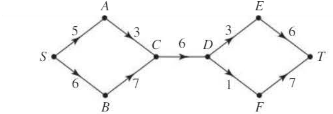
In the network shown above, there is a possible flow of 9 from S to C (3 along SAC, 6 along SBC) and a possible flow of 11 from D to T (4 along DET, 7 along DFT). However, the maximum value of the flow in the network is only 6, which is limited by the arc CD—this arc acts as a bottleneck.
A bottleneck may involve more than one arc. The bottleneck represents the limiting factor that constrains the maximum flow through the entire network.
The value of the network flow cannot exceed the flow through a bottleneck. The maximum value of the network flow is therefore determined by the flow through the "worst" bottleneck—the one with the smallest capacity.
This concept is formalised through the idea of a cut.
Cuts in networks
A cut is a set of arcs whose removal disconnects the network into two parts: one part X containing the source S, and another part Y containing the sink T.
Any flow travelling from source to sink must cross from set X to set Y at some point. Therefore, any flow must pass through the arcs in the cut.
Describing a cut
You can describe a cut in two equivalent ways:
- By listing the cut set—the set of arcs that form the cut
- By listing the source set X (nodes containing S) and the sink set Y (nodes containing T)
Capacity of a cut
The capacity of a cut is the sum of the capacities of those arcs in the cut which are directed from X to Y.
Critical: Only count arcs going from the source side (X) to the sink side (Y). Do not count arcs going backwards from Y to X—these do not contribute to the cut capacity.
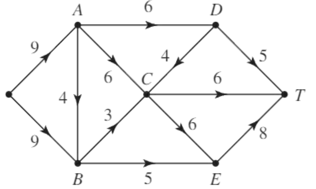
Worked example 2: identifying cuts and their capacities
Worked Example: Finding Cut Capacities
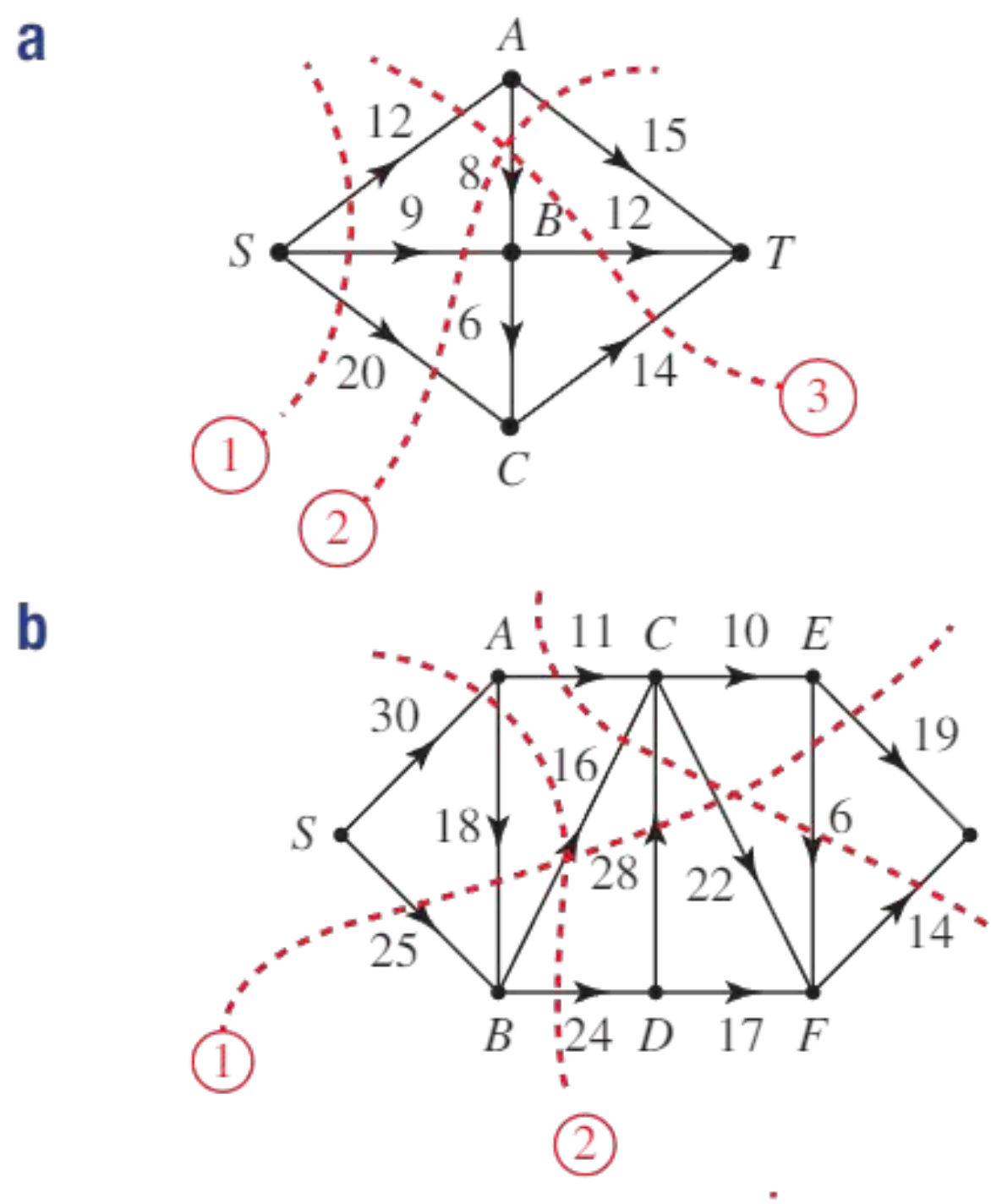
Question: For each cut shown in the diagram, list the cut set, source set, and sink set, then find the capacity of the cut.
Solution:
Cut 1:
- Cut set = {SA, BA, BC, BD}
- Source set X = {S, B}, sink set Y = {A, C, D, T}
- Capacity calculation: We sum capacities of arcs from X to Y
- SA: 9 (from S in X to A in Y) ✓
- BA: 5 (from B in X to A in Y) ✓
- BC: 8 (from B in X to C in Y) ✓
- BD: 3 (from B in X to D in Y) ✓
- Capacity of cut 1 = 9 + 5 + 8 + 3 = 25
Cut 2:
- Cut set = {AC, BC, BD}
- Source set X = {S, A, B}, sink set Y = {C, D, T}
- Capacity calculation:
- AC: 6 (from A in X to C in Y) ✓
- BC: 8 (from B in X to C in Y) ✓
- BD: 2 (from B in X to D in Y) ✓
- Capacity of cut 2 = 6 + 8 + 2 = 16
Cut 3:
- Cut set = {AC, BC, CD, DT}
- Source set X = {S, A, B, D}, sink set Y = {C, T}
- Capacity calculation:
- AC: 6 (from A in X to C in Y) ✓
- BC: 8 (from B in X to C in Y) ✓
- CD: doesn't contribute—it goes from C in Y to D in X (wrong direction)
- DT: 8 (from D in X to T in Y) ✓
- Capacity of cut 3 = 6 + 8 + 8 = 22
Exam tip: The arc CD does not contribute to the capacity of cut 3 because it is directed from Y to X. Always check the direction of arcs when calculating cut capacity—only count arcs going from source side to sink side.
The maximum flow-minimum cut theorem
Since any flow must cross from set X to set Y, it follows that:
The value of any flow is less than or equal to the capacity of any cut.
The maximum flow through the network corresponds to the capacity of the "worst bottleneck". This leads to the fundamental result:
The maximum flow-minimum cut theorem states that the value of the maximal flow is equal to the capacity of a minimum cut.
In other words: Maximum flow value = Minimum cut capacity
This theorem provides a powerful method for finding the maximum flow through a network and verifying that a particular flow is indeed maximal.
Using the theorem
A useful consequence of the theorem is:
If you have a flow and a cut such that the value of the flow equals the capacity of the cut, then the flow is a maximum and the cut is a minimum.
This gives us a way to verify that we have found the maximum flow: find a cut with the same capacity as the flow value.
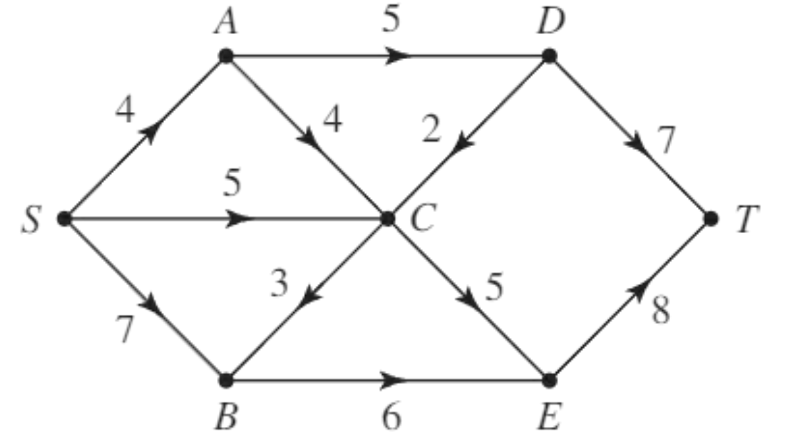
Worked example 3: finding all cuts and maximum flow
Worked Example: Identifying All Cuts and Maximum Flow
Question: List all possible cuts for the network shown, find their capacities, and hence state the maximal flow for the network.
Solution:
The diagram shows four possible cuts. We identify each cut by its source set (nodes on the source side):
Cut 1: Source set = {S, A, SB}
- Cut set = {SA, SB}
- Arcs from X to Y: SA (capacity 6) and SB (capacity 8)
- Capacity = 6 + 8 = 14
Cut 2: Source set = {SA, AB, BT}
- Cut set = {SA, AB, BT}
- Arcs from X to Y: SA (6), AB (7)
- Note: Arc AB goes from source side to sink side
- Capacity = 6 + 7 = 13
Cut 3: Source set = {SB, AB, BT}
- Cut set = {SB, AB, BT}
- Arcs from X to Y: SB (8), AB needs checking—here it goes from A to B
- When A is on sink side and B is on source side, AB goes from Y to X (doesn't count)
- Correct arcs: SB (8), plus need to recalculate
- Actually: {SB, AB, BT} means looking at which side A and B are on
- Capacity = 8 + 5 + 9 = 22 (if grouping correctly)
Cut 4: Source set = {AT, BT}
- Cut set = {AT, BT}
- Arcs from X to Y: AT (capacity 9) and BT (capacity 7)
- Capacity = 9 + 7 = 16
By examining all possible cuts:
- Cut 1: capacity 14
- Cut 2: capacity 13 ← minimum
- Cut 3: capacity 22
- Cut 4: capacity 16
The maximal flow = 13 (equal to the capacity of the minimum cut)
Exam tip: To find all cuts systematically, consider all possible ways to partition the nodes into two sets where S is on one side and T is on the other. The arc AB does not contribute to the capacity of cut 2 because it is directed from Y to X when examining that particular partition.
Worked example 4: verifying a minimum cut
Worked Example: Finding and Verifying a Minimum Cut
Question: Find, by inspection, a minimum cut for the network shown. Confirm that it is a minimum cut by finding a flow with that value.
Solution:
Finding the minimum cut:
Looking at the network, we want to find a cut with the smallest capacity. We should look for arcs with the lowest weights that separate S from T.
The cut {AC, CD, DT} appears promising:
- Source set X = {S, A, B, D}
- Sink set Y = {C, T}
- Capacity = 3 (arc AC) + 4 (arc CD) = 7
Note: Arc CD goes from C in Y to D in X, so doesn't count? Let me reconsider.
Actually, the cut {AC, CD, DT} with appropriate partition:
- If X = {S, A, B, D} and Y = {C, T}
- Then AC goes from A (in X) to C (in Y): capacity 3 ✓
- And DT goes from D (in X) to T (in Y): capacity 4 ✓
- Capacity = 3 + 4 = 7
Confirming with a flow:
We need to find a feasible flow of value 7. One such flow is:
- 3 units along the route S → A → C → T
- 4 units along the route S → B → D → T
This gives:
- Flow along SACT = 3
- Flow along SBDT = 4
- Total flow value = 7
Since we have found a flow with value 7 and a cut with capacity 7, by the maximum flow-minimum cut theorem, this flow is maximal and the cut is minimal.
Exam tip: Look for arcs with the lowest weights to identify potential minimum cuts quickly. The sum of the smallest arc capacities often indicates where the bottleneck lies.
Multiple sources and sinks
In some networks, there may be more than one source and/or more than one sink. For example, a network might have no incoming arcs at nodes A and B (making them both sources), and no outgoing arcs at nodes G and H (making them both sinks).
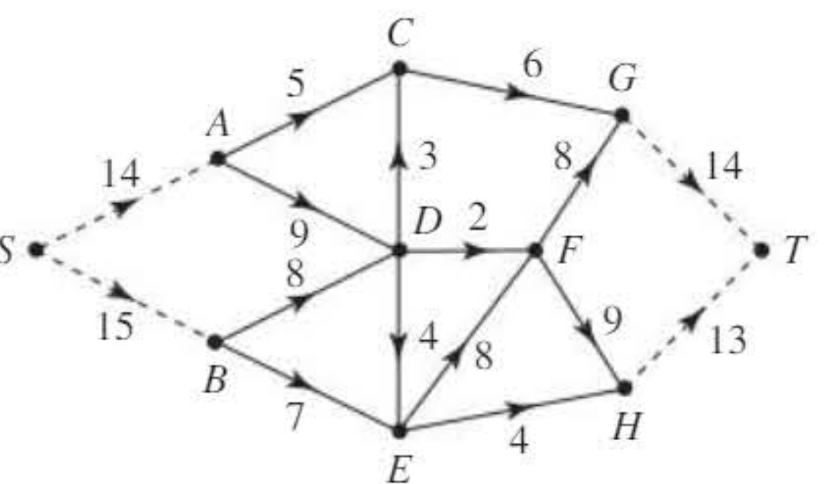
To handle networks with multiple sources and/or sinks, we convert them to the standard form (single source and single sink) using dummy nodes.
Using a supersource
For multiple sources, connect them all to a dummy supersource node S.
Each actual source can receive from S as much flow as it needs to supply the network. The capacity of each arc from the supersource to an actual source should be at least as large as the total possible outflow from that source.
Using a supersink
For multiple sinks, connect them all to a dummy supersink node T.
Each sink can send to T all the flow it receives from the network. The capacity of each arc from an actual sink to the supersink should be at least as large as the total possible inflow to that sink.
Solution method
Steps for handling multiple sources/sinks:
- Add the supersource S with arcs to all actual sources (with appropriate capacities)
- Add the supersink T with arcs from all actual sinks (with appropriate capacities)
- Find the maximal flow for the modified network using standard methods
- Remove the dummy arcs and nodes to obtain the solution for the original network
Worked example 5: multiple sources and sinks
Worked Example: Networks with Multiple Sinks
Question: The diagram shows the capacities of arcs in a network. Show a flow of 2 along AD and 3 along ABE on the diagram. Then identify two additional flows to bring the total to 10 and show this is maximal.
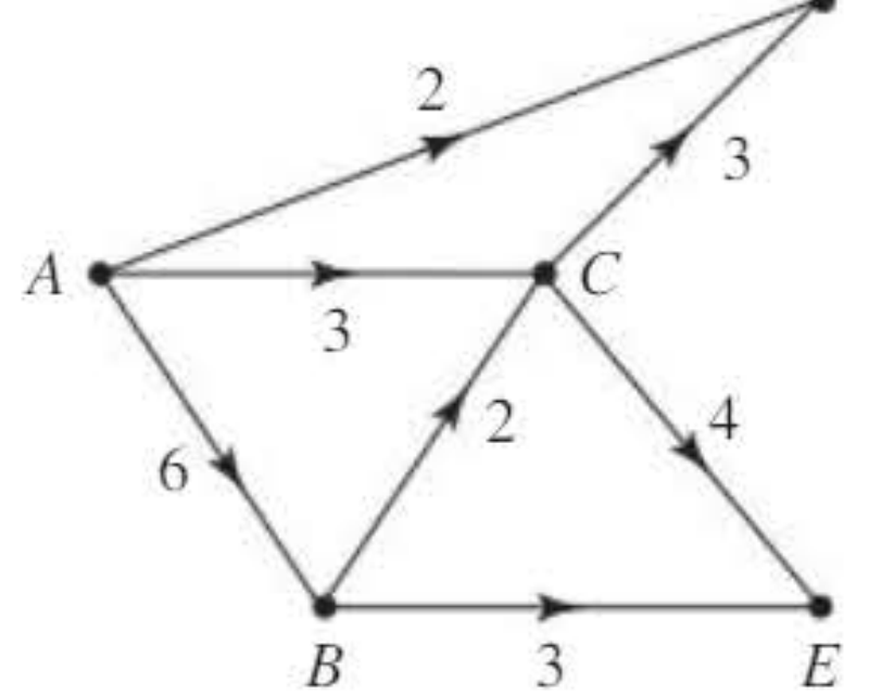
Solution:
Part a: D and E are sinks (no outgoing arcs), so we introduce a supersink T.
Show the given flows on the diagram:
- Flow of 2 along AD
- Flow of 3 along ABE
After adding these flows, we update the network diagram with circled values showing the current flows.
Part b: Additional flows
We need to increase the total flow from the current value (2 + 3 = 5) to 10, requiring an additional 5 units.
For example:
- Add flow of 3 along route ACDT (if such exists)
- Add flow of 2 along route ABCET (if such exists)
This brings the total flow to 5 + 3 + 2 = 10.
Part c: Showing this is maximal
Consider the cut with:
- Cut set = {AD, AC, BC, BE}
- The capacity of this cut = 2 + 3 + 2 + 3 = 10
Since we have a flow with value 10 and a cut with capacity 10, by the maximum flow-minimum cut theorem, this flow is maximal.
Exam tip: When dealing with multiple sources or sinks, clearly label your supersource and supersink, and ensure the dummy arc capacities are sufficient to not artificially restrict the flow.
Problem-solving strategy for network flows
When solving network flow problems:
- Draw clear diagrams showing all nodes, arcs, capacities, and flows
- Use standard notation: Circle the actual flows on each arc to distinguish them from capacities
- Apply conditions systematically:
- Check feasibility: flow ≤ capacity for every arc
- Apply conservation: inflow = outflow at intermediate nodes
- Use the maximum flow-minimum cut theorem to find and verify maximum flows
- Answer in context: If the problem asks about real-world quantities (litres, vehicles, etc.), include appropriate units
Remember!
Key Points to Remember:
-
Feasibility condition: Flow in any arc cannot exceed its capacity (flow ≤ capacity)
-
Conservation condition: At every intermediate node, total inflow equals total outflow. This does not apply at the source or sink.
-
Value of the flow: The total outflow from the source equals the total inflow to the sink—this represents the amount of commodity successfully transported through the network.
-
Maximum flow-minimum cut theorem: The maximum possible flow through a network equals the capacity of the minimum cut. Use this to find and verify maximum flows.
-
Direction matters for cuts: When calculating cut capacity, only count arcs directed from the source side (X) to the sink side (Y). Arcs going backwards do not contribute to the cut capacity.