Network Flows 2 (AQA A-Level Further Maths): Revision Notes
Network Flows 2
Introduction and recap
This section builds upon network flow concepts introduced in Chapter 12. We work with directed networks where a commodity flows from a source (usually called ) to a sink (usually called ).
Key definitions
Source: The starting point where the commodity flows from, typically labelled .
Sink: The ending point where the commodity flows to, typically labelled .
Capacity: The maximum amount of flow that can pass through an arc. Each arc has a specified capacity value.
Flow: The actual amount of commodity passing through an arc. The flow cannot exceed the arc's capacity.
Feasibility condition: The flow along any arc must not exceed its capacity. Mathematically, for any arc, flow ≤ capacity.
Conservation condition: At every node (except the source and sink), the total inflow must equal the total outflow. This ensures flow is neither created nor destroyed at intermediate nodes.
Saturated arc: An arc where the flow equals its capacity. No additional flow can pass through a saturated arc without reducing flow elsewhere.
Value of the flow: The total amount leaving the source , which equals the total amount entering the sink . This represents the overall throughput of the network.
Capacity of the network: The maximum possible value of flow that can be achieved in the network.
These fundamental definitions form the basis for all network flow problems. Understanding the distinction between capacity (maximum possible) and flow (actual amount) is essential for solving these problems effectively.
Cuts in networks
A cut separates the network into two parts: nodes connected to the source and nodes connected to the sink.
You can describe a cut in two ways:
- By listing the arcs in the cut set (arcs crossing from source side to sink side)
- By listing nodes in the source set and nodes in the sink set
Capacity of a cut: The sum of capacities of arcs directed from the source set to the sink set .
Example: Identifying a Cut
In a network, if cut 2 has cut set , source set and sink set , then the capacity equals the sum of capacities of arcs , , and going from to .
Maximum flow, minimum cut theorem
The maximum flow through a network equals the capacity of a minimum cut. This fundamental theorem provides both:
- A method to verify that a flow is maximal
- An upper bound on the possible flow
Key Principle: Maximum Flow = Minimum Cut
The value of the maximal flow = the capacity of a minimum cut
If you find a flow and a cut such that:
then the flow is maximum and the cut is minimum.
This theorem allows you to prove that a flow is maximal without exhaustively checking all possible paths.
Flow augmentation
To find the maximum flow, start with an initial flow (which could be zero) and systematically increase it. This process is called flow augmentation.
The flow augmentation process involves:
- Starting with an initial feasible flow
- Looking for ways to increase (augment) the flow
- Repeating until no further augmentation is possible
- The resulting flow is maximal
The key challenge is identifying how to increase the flow systematically. This is where flow-augmenting paths become important, and the labelling procedure provides a systematic approach to finding them.
The labelling procedure
The labelling procedure overcomes the difficulty of spotting flow-augmenting paths, especially when flows need to be reduced on some arcs. This systematic method helps identify opportunities to increase overall flow.
Potential flow and potential backflow
Consider an arc with capacity 12 and current flow of 8:
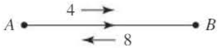
- Potential flow: The amount by which flow can be increased = capacity − current flow =
- Potential backflow: The amount by which flow can be decreased = current flow =
The labelling procedure shows these as two arrows:
- A forward arrow (rightward) showing the potential flow (4)
- A backward arrow (leftward) showing the potential backflow (8)
The total of these two values equals the arc's capacity. This dual representation allows us to see both how much more flow can be added and how much existing flow can be redirected.
Finding flow-augmenting paths
Definition: A flow-augmenting path is a route from to where all arrows pointing forward along the route have non-zero values.
The smallest non-zero value along the path determines how much extra flow can be sent along that route.
Key Procedure for Flow Augmentation:
- Label each arc with its potential flow (forward arrow) and potential backflow (backward arrow)
- Search for a path from to where all forward arrows are non-zero
- The minimum forward arrow value gives the extra flow possible
- Update the network by:
- Reducing forward arrows by this amount
- Increasing backward arrows by this amount
- Repeat until no flow-augmenting path exists
Worked example 1: Basic flow augmentation
Worked Example: Basic Flow Augmentation
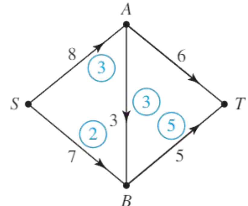
Problem: Starting with an initial flow of 3 along and 2 along , find a maximal flow through this network.
Solution:
The initial flow shows 3 units along path and 2 units along path .
Subtracting these flows from the capacities shows the spare capacity remaining on each arc. A flow of 5 is possible along path , making a flow-augmenting path.
After adding this flow of 5, check for further flow-augmenting paths. There is no obvious path, but we can increase flow on and by 1 while reducing flow on by 1.
The overall effect increases the network flow by 1. This gives a total flow of .
The arcs and are now saturated (flow equals capacity), so the flow is maximal.
Final flow: 11 units
The circled values in the final diagram show the flow in each arc.
Worked example 2: Using the labelling procedure
Worked Example: Using the Labelling Procedure for Larger Networks
Problem: Taking a flow of 16 along and 10 along as the initial flow, use flow-augmenting paths to find a maximal flow for this network. Record your working in a table.
Solution:
The initial flow is shown with blue arrows indicating potential flows and backflows:
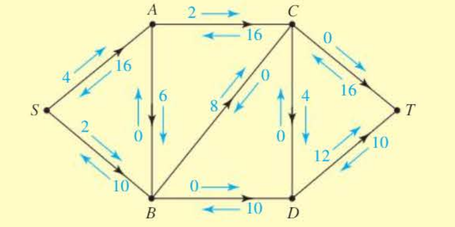
Path is a flow-augmenting path with potential flow of 2 (the minimum forward arrow value along this route).
| Augmenting path | Flow |
|---|---|
| 2 |
Update the labels to include this flow:
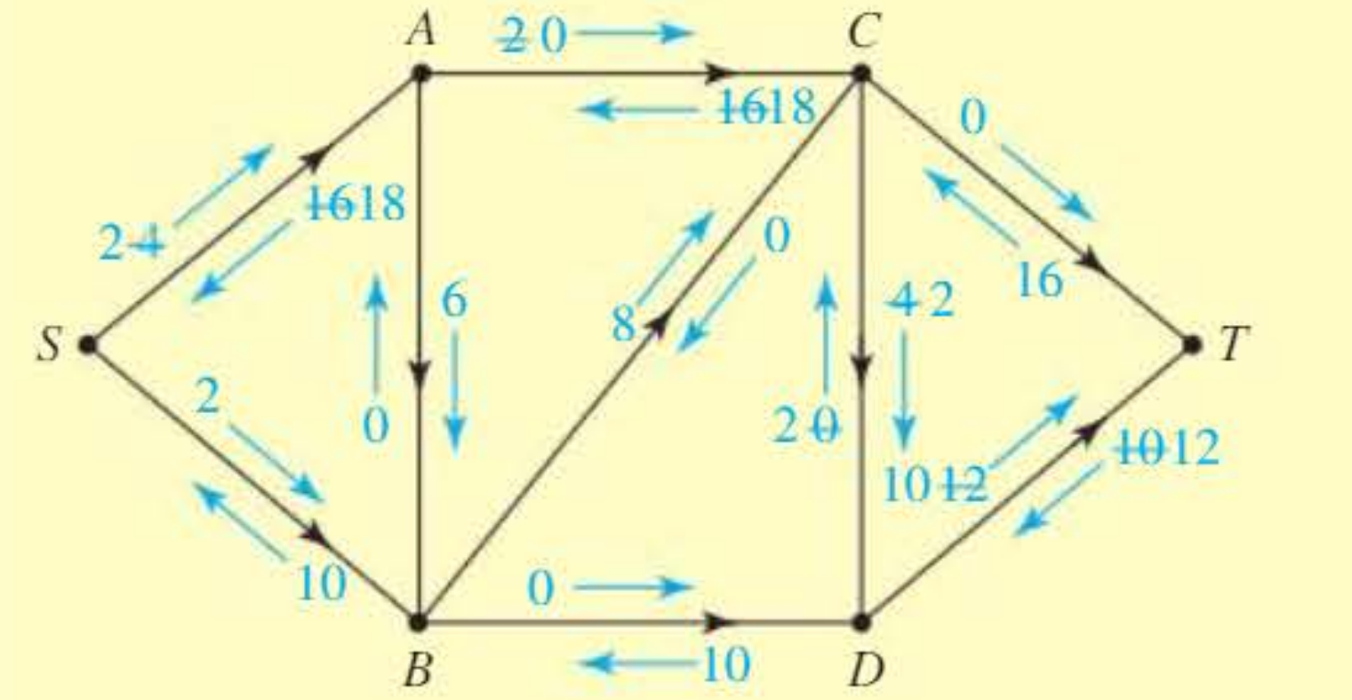
Path is also a flow-augmenting path with potential flow of 2.
| Augmenting path | Flow |
|---|---|
| 2 | |
| 2 |
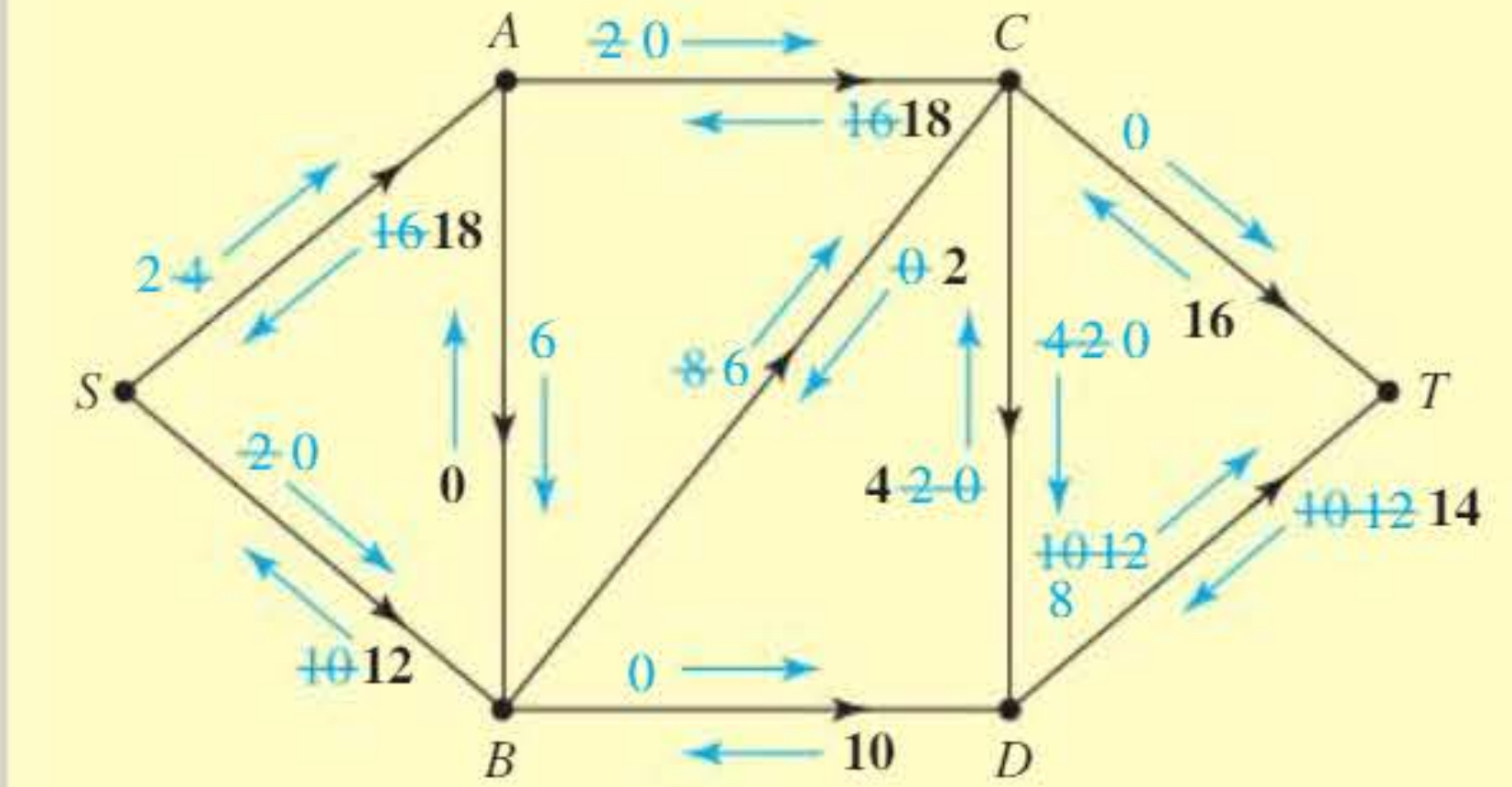
After updating the labels, there is no flow-augmenting path available, so the flow is maximal.
The flow has been increased by a total of 4, so the maximal flow is units.
Final maximal flow: 30 units
Networks with minimum capacities
Some networks have arcs with both minimum and maximum capacities. For example, pipelines carrying flammable gas may require a minimum flow for safety reasons.
Each arc shows two values: minimum capacity and maximum capacity (e.g., 2,4 means minimum 2, maximum 4).
Finding an initial feasible flow
With minimum capacities, you cannot start with zero flow. The first task is finding an initial feasible flow where:
- The flow through each node is compatible with both minimum and maximum total inflows and outflows
- Each arc's flow satisfies its minimum and maximum constraints
Look at this partial network:
The values shown on each arc give the minimum and maximum permissible flow. At least 5 units must flow through this node (sum of minimum incoming capacities). No more than 11 units can flow (sum of maximum outgoing capacities).
Watch Out for Infeasible Networks!
In rare cases, no feasible flow exists. This happens when:
- Maximum outflow < minimum inflow, or
- Maximum inflow < minimum outflow
Always check that an initial feasible flow is possible before attempting to find the maximum flow.
Using the labelling procedure with minimum capacities
Once you have found an initial flow, use the labelling procedure as before. The only difference is that potential flow and backflow must be compatible with the minimum and maximum flows in each arc.
Example: Potential Flow and Backflow with Minimum Capacities
For an arc with a flow of 6 units on arc with capacities (3,8):
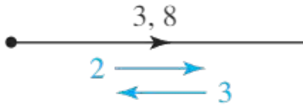
- Flow can be increased by 2 (maximum 8 − current 6)
- Flow can be decreased by 3 (current 6 − minimum 3)
You can find the flow (6) from the diagram as:
- (minimum capacity (3) + potential backflow (3)), or
- (maximum capacity (8) − potential flow (2))
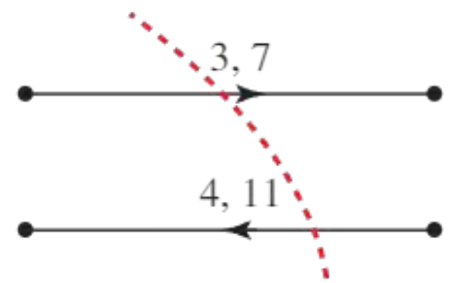
Capacity of cuts with minimum capacities
When calculating cut capacity with minimum capacities, you must account for arcs directed from sink set to source set:
For example, if 7 + 9 = 16 could flow left to right through a cut, but at least 4 must flow right to left, then the cut capacity is .
This subtraction accounts for the fact that some flow must go in the opposite direction, reducing the net capacity of the cut.
Worked example 3: Network with minimum capacities
Worked Example: Network with Minimum Capacities
Problem: For this network, an initial feasible flow is 3, 4, 5.
a) Use flow augmentation to find a maximal flow.
b) Confirm the result using the maximum flow, minimum cut theorem.
Solution:
a) The labelling shows the initial flow:
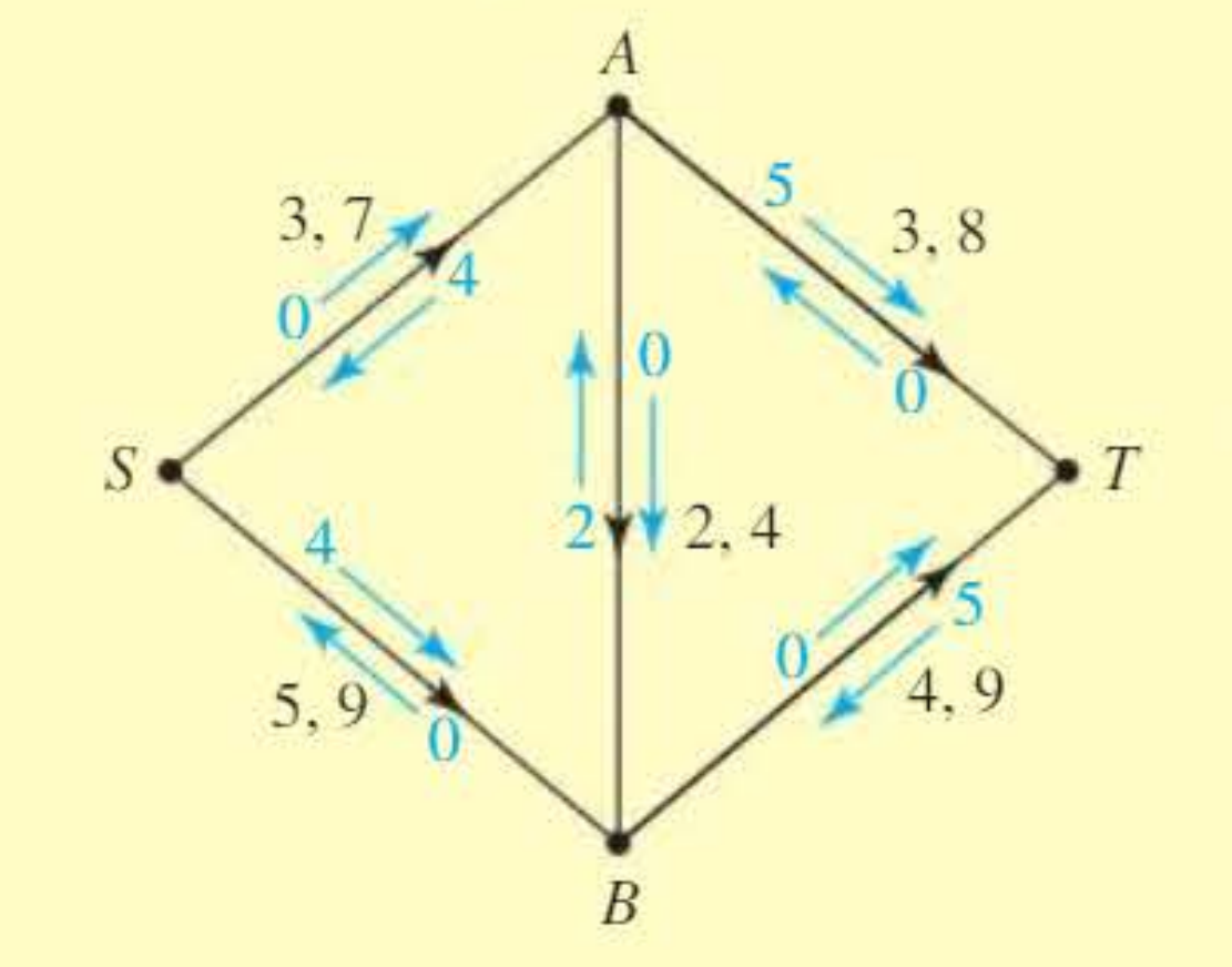
The forward arrows have minimum value 2 along route , making it a flow-augmenting path with potential flow of 2.
After updating labels, the forward arrows along route all have minimum value 1.
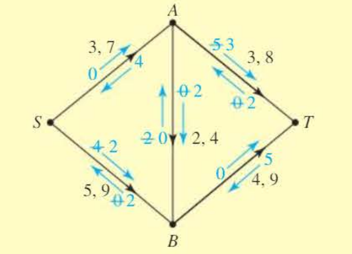
After adding this flow of 1, there are no more flow-augmenting paths, so the flow is maximal.
The total flow is units (note: this simplifies to the flows actually passing through the network).
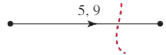
b) The cut shown in the diagram has capacity:
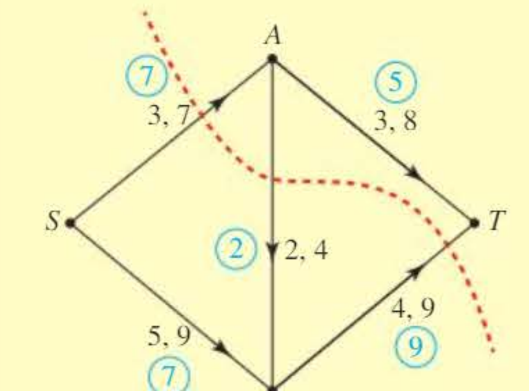
There is a flow of 14 and a cut of 14, so by the maximum flow, minimum cut theorem, this flow is maximal.
Multiple sources and sinks
When a network has more than one source or sink, introduce a supersource or supersink to convert it to standard form.
Adding a supersource and supersink
Supersource: A dummy source node connected to all actual sources with arcs whose capacities match the actual sources' outflow capacities.
Supersink: A dummy sink node connected to all actual sinks with arcs whose capacities match the actual sinks' inflow capacities.
This technique converts a multi-source, multi-sink problem into a standard single-source, single-sink problem that can be solved using the methods we've already learned. After finding the solution, you can remove the dummy nodes to show the flow in the original network.
Worked example 4: Multiple sources and sinks
Worked Example: Network with Multiple Sources and Sinks
Problem: Use an initial flow and flow augmentation to find a maximal flow through this network (which has two sources and two sinks).
Solution:
Introduce a supersource and supersink , with capacities 14, 15, 14 and 13.
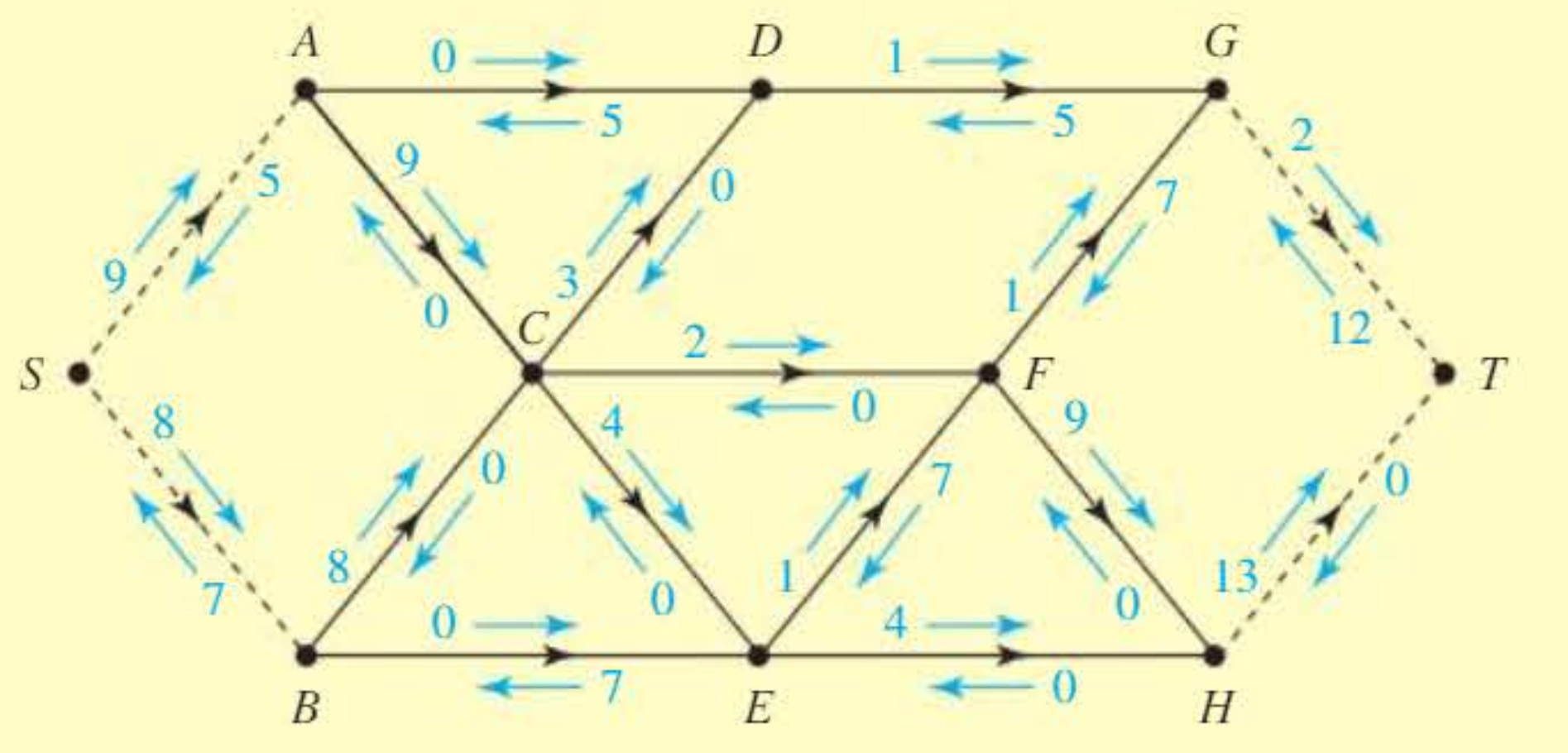
The capacity of and match the total outflow capacity of and . The capacities of and match the total inflow capacity of and .
Take as initial flows 5 and 7.
After labelling, there is a flow-augmenting path with capacity 4.
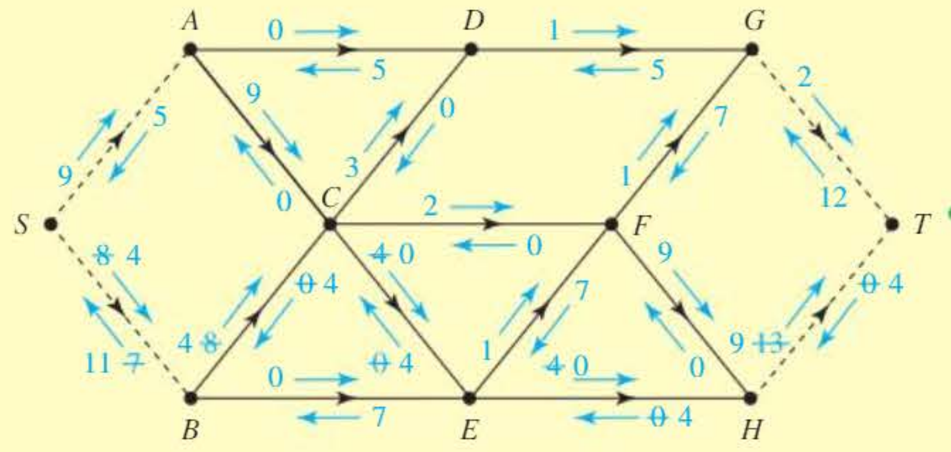
After updating and labelling again, there is a flow-augmenting path with capacity 2.
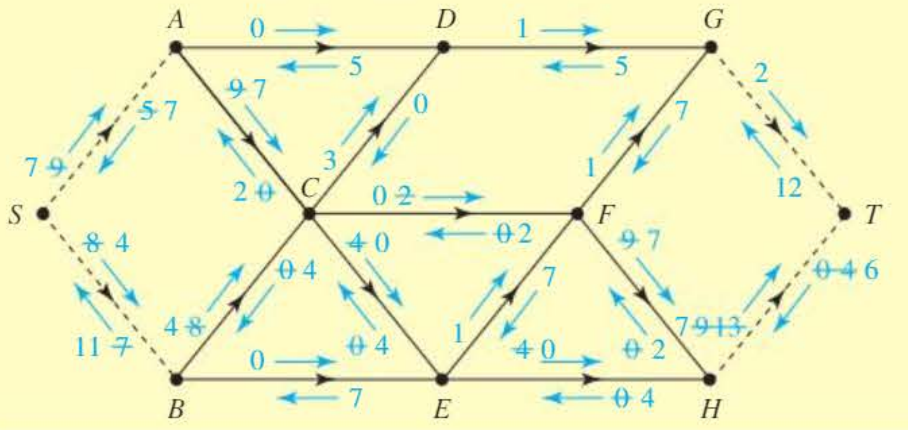
After this update, there is a flow-augmenting path with capacity 1.
, , and are now saturated, so the flow is maximal.
The total network flow is units.
You could now remove the dummy nodes and arcs to show the solution for the original network.
Final maximal flow: 19 units
Node capacity restrictions
Sometimes there is a restriction on the flow through a node (e.g., a pumping station capacity being less than the incoming and outgoing pipe capacities).
Modelling node restrictions
To deal with node restrictions, draw a modified network with an extra arc representing flow through the restricted node:
Method for Handling Node Capacity Restrictions:
- Split the restricted node into two nodes (e.g., becomes and )
- All inflows go to the first node
- All outflows emerge from the second node
- Connect to with an arc having capacity equal to the node's restriction
This ensures that the flow through the node cannot exceed its capacity.
Worked example 5: Network with node capacity restrictions
Worked Example: Network with Node Capacity Restrictions
Problem: Find the maximal flow through this network, given that nodes and have capacities of 5 and 4, respectively.
Solution:
The modified network splits nodes and :
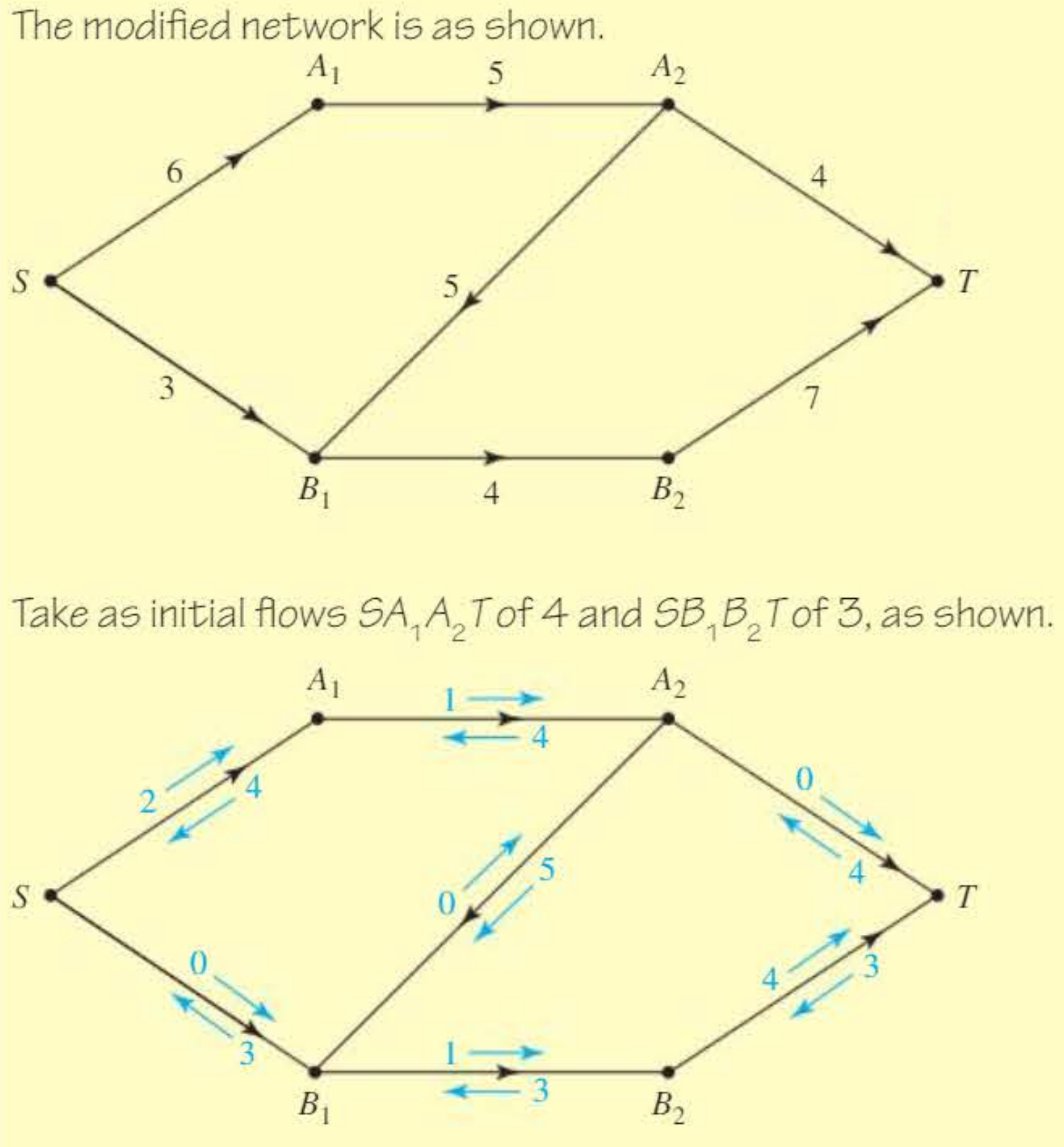
Take as initial flows of 4 and of 3, as shown.
There is a flow-augmenting path with capacity 1.
On the updated diagram, the arcs and are saturated, so the flow is maximal.
The total network flow is 8 units.
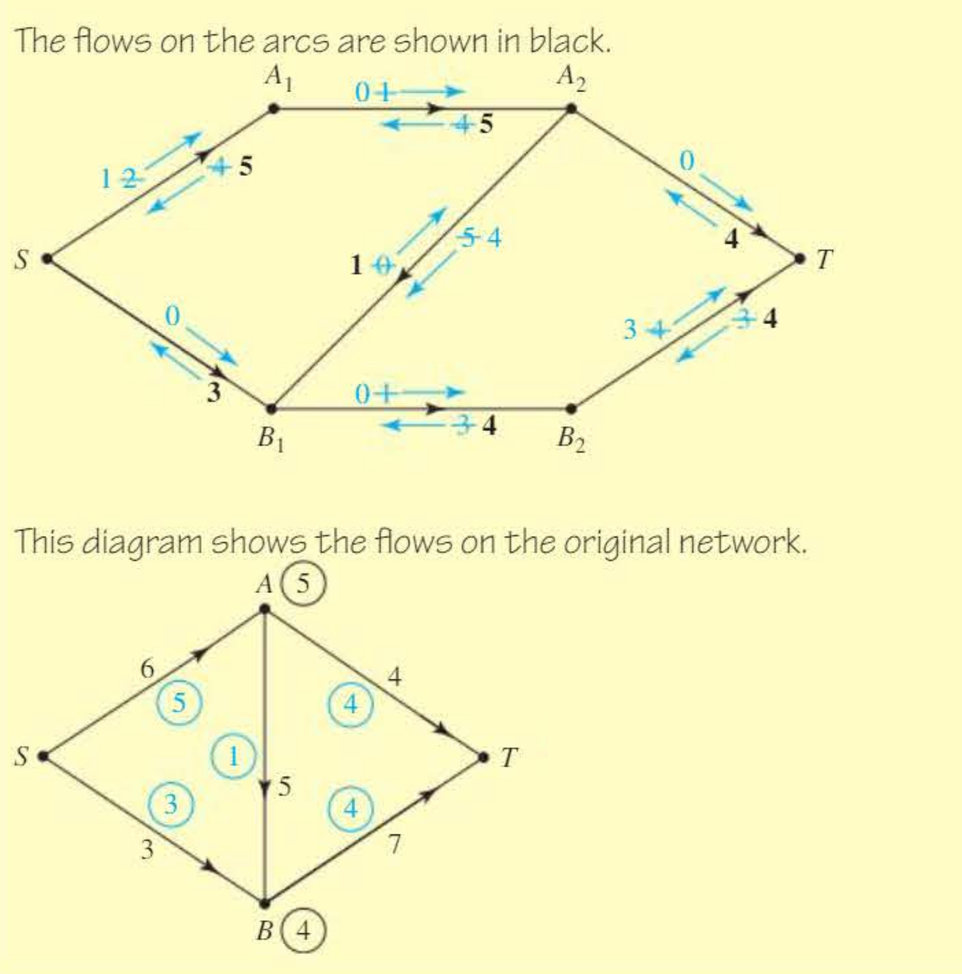
The final diagram shows the flows on the original network (without the split nodes).
Problem-solving strategy
Step-by-Step Strategy for Network Flow Problems:
-
Use clear network diagrams. Draw the network neatly with all nodes and arcs clearly labelled.
-
Find an initial flow and label your diagram. Start with any feasible flow (considering minimum capacities if present). Label each arc with current flow or with potential flow/backflow arrows.
-
Find a flow-augmenting path and update the labels to include this flow. Identify a path from to where all forward arrows are positive. Add the minimum forward value to the flow. Update all labels accordingly.
-
Continue until there is no flow-augmenting path. Repeat step 3 until no valid augmenting path exists. The flow is then maximal.
-
If required, use the maximum flow, minimum cut theorem to confirm your flow is maximal. Find a cut whose capacity equals your flow value. This proves maximality.
-
Answer the question. State the maximal flow value clearly. If node restrictions or supersources were used, show the final flow on the original network.
Remember!
Key Points to Remember:
-
The maximum flow equals the minimum cut capacity in any network. Use this to verify your answer.
-
A flow-augmenting path requires all forward arrows to have non-zero values. The minimum forward value determines the extra flow.
-
The labelling procedure systematically identifies augmenting paths by showing potential flows (forward arrows) and potential backflows (backward arrows) on each arc.
-
With minimum capacities, ensure your initial flow is feasible and remember that cut capacity is calculated as (maximum from to ) − (minimum from to ).
-
For multiple sources or sinks, introduce a supersource or supersink with appropriate connecting capacities to convert to standard form.
-
For node capacity restrictions, split the restricted node into two nodes connected by an arc with capacity equal to the node's limit.