The normal ECG waveform (AQA A-Level Physics): Revision Notes
The normal ECG waveform
Introduction to electrocardiography
An electrocardiograph (ECG) is a graphical display showing the heart's electrical activity as a function of time. The electrical impulses generated by the heart spread through surrounding body tissues and fluids, allowing them to be detected by electrodes placed on the skin surface.
The ECG provides a non-invasive method to monitor cardiac function by detecting the electrical signals that coordinate heart muscle contractions. These signals can be recorded from the body surface because body fluids act as electrical conductors.
Measuring the ECG signal
Electrode placement and contact
Obtaining accurate ECG measurements requires careful electrode placement and good electrical contact with the skin. Several techniques are used to ensure reliable readings:
The skin surface is gently prepared by removing dead cells through light abrasion. This improves the electrical connection between the electrode and the underlying living tissue. An electrically conducting gel is then applied to further enhance contact quality.
Electrode Selection is Critical
Silver electrodes coated with silver chloride are the standard choice for ECG measurements. These electrodes are chemically stable and do not react with substances naturally produced by the skin, preventing unwanted chemical reactions that could affect the signal quality.
Adhesive tape secures the electrodes firmly in place. This prevents voltage spikes that would otherwise occur due to electrostatic effects when the electrodes move relative to the skin.
Signal amplification and interference
The electrical signals detected at the skin surface are extremely small, typically around 1 mV in amplitude. This is much smaller than the action potentials within the heart muscle itself, which reach tens of millivolts. Therefore, a high-gain amplifier is required to boost these signals to measurable levels.
However, amplification increases both the desired signal and any unwanted noise. A particular challenge comes from electromagnetic interference. Mains-operated equipment nearby produces alternating voltages at 50 Hz, which can induce small electromotive forces (emfs) in the ECG equipment.
Combating Electromagnetic Interference
Several precautions are essential to minimize interference:
- All electrical leads are screened to block external electromagnetic fields
- The ECG equipment housing is carefully shielded
- The patient must remain relaxed and still during measurement to minimize motion-related artifacts
These measures ensure that the recorded signal accurately represents cardiac electrical activity rather than external noise.
The resulting voltage trace can be viewed in real time on a screen and printed as a permanent record.
Structure of the normal ECG waveform
The characteristic PQRST pattern
A typical ECG waveform from a healthy heart displays a distinctive PQRST pattern. One complete cardiac cycle, lasting approximately 0.6 seconds, shows three main features labeled as waves:
The P wave appears as a small positive deflection at the beginning of the cycle. The QRS complex follows, showing a brief negative deflection (Q), a sharp positive peak (R), and another negative deflection (S). Finally, the T wave appears as a broader positive deflection before the cycle repeats.
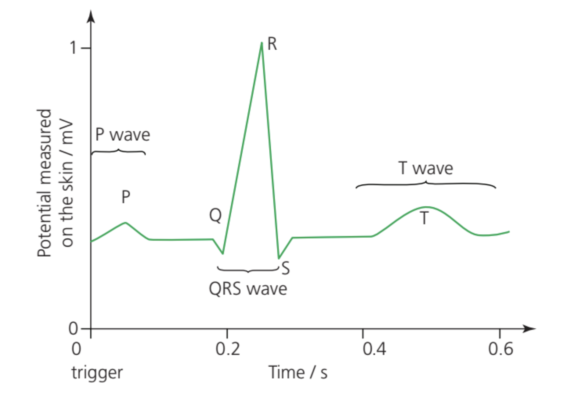
Time scale and amplitude
The amplitude of the ECG signal measured at the skin surface is approximately 1 mV. This is considerably smaller than the action potentials occurring within the heart muscle cells themselves, which reach amplitudes of tens of millivolts.
A complete cardiac cycle in a resting individual typically takes around 0.6 seconds, corresponding to a heart rate of approximately 100 beats per minute. The time intervals between different waves provide important diagnostic information about the sequence and timing of cardiac electrical events.
Physiological basis of ECG features
Electrical activity in the heart
The heart muscle is stimulated by pulses of electrical potential in the muscle cells. During electrical activity, heart muscle cells undergo cycles of depolarisation and repolarisation:
- Depolarisation occurs when the cell membrane potential rises from its resting value to a positive value, triggering muscle contraction.
- Repolarisation is the return to the resting membrane potential, allowing the muscle to relax.
Heart vs. Nerve Action Potentials
In the heart, the action potential travels more slowly than in nerve fibers and lasts longer (approximately 0.2 s compared to 5 ms in nerve cells). This extended duration allows the heart muscle to relax completely before the next contraction begins, ensuring efficient pumping action.
The P wave
The P wave represents the depolarisation of the atrial muscle cells. This small change in potential corresponds to electrical activity spreading across the upper chambers of the heart (the atria), causing them to contract. The relatively small amplitude of the P wave reflects the smaller mass of the atrial muscle compared to the ventricles.
The QRS complex
The QRS wave is the most prominent feature of the ECG trace. It represents the depolarisation of the ventricular muscle cells and corresponds to contraction of the ventricles. The large amplitude of this wave reflects the substantial muscle mass of the ventricular walls, which must generate sufficient pressure to pump blood throughout the body.
Interestingly, the repolarisation of the atria occurs during this time but is completely masked by the much larger electrical signals from the ventricles. This is why the atrial repolarisation does not appear as a distinct feature on the ECG trace.
The T wave
The T wave represents the repolarisation of the ventricular muscle cells, corresponding to relaxation of the ventricles. This broader, lower-amplitude wave indicates the return of ventricular muscle cells to their resting electrical state, preparing them for the next cardiac cycle.
Clinical applications
Determining pulse rate
The repeating pattern of the ECG trace enables straightforward determination of the pulse rate, defined as the number of ventricular contractions per minute. By measuring the time interval between successive QRS complexes, the heart rate can be calculated precisely.
Worked Example: Calculating Pulse Rate from ECG
Given: QRS complexes are separated by 1.0 seconds
Step 1: Identify that pulse rate = number of beats per minute
Step 2: Calculate beats per minute
- Time per beat = 1.0 s
- Beats per minute = 60 s ÷ 1.0 s = 60 beats per minute
Interpretation:
- Shorter intervals indicate higher pulse rates
- Longer intervals indicate lower pulse rates
Diagnostic information
The shape and timing of the ECG waveform provide valuable diagnostic information about heart function. Abnormalities in the amplitude, duration, or timing of the P, QRS, or T waves can indicate various cardiac conditions. Medical professionals analyse these features to assess heart health and identify potential problems such as arrhythmias, conduction defects, or muscle damage.
Key Points to Remember:
- An ECG is a graphical display of electrical activity in the heart, measured using electrodes on the skin surface
- Good electrical contact is achieved using silver/silver chloride electrodes, conducting gel, and skin preparation
- The ECG signal (~1 mV amplitude) requires high-gain amplification and careful shielding from 50 Hz mains interference
- The normal ECG shows a characteristic PQRST pattern: P wave (atrial depolarisation), QRS complex (ventricular depolarisation), and T wave (ventricular repolarisation)
- The QRS complex is the largest feature, reflecting the greater muscle mass of the ventricles compared to the atria
- Time intervals between waves provide important diagnostic information about cardiac function