Core practical: Electrical circuits (Edexcel GCSE Physics): Revision Notes
📚 Revision Notes
Core practical: Electrical circuits
infoNote
This practical investigates how resistors behave in series and parallel circuits, measuring the potential difference, current, and resistance. The experiment also explores how resistance changes when resistors are combined in different ways.
infoNote
Doing the experiment:
- Set up the circuit, connecting a resistor, voltmeter, ammeter, and power supply.
- Ensure the ammeter is connected in series and the voltmeter is connected in parallel with the resistor.
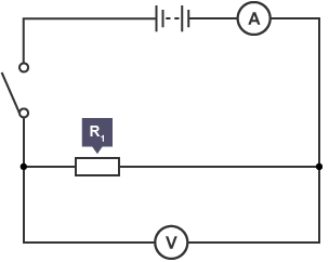
- Turn on the power supply and close the switch.
- Record the readings from the voltmeter (potential difference, ) and the ammeter (current, ).
- Calculate the resistance of the resistor using the formula:
where:
- = resistance (in ohms, Ω)
- = potential difference (in volts, V)
- = current (in amperes, A)
- Change the resistor and repeat steps 2–4 to find the resistance of the second resistor.
- Arrange the two resistors in series.
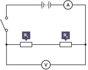
- Close the switch and record the voltmeter and ammeter readings again.
- Determine the total resistance of both resistors in series using:
- Arrange the two resistors in parallel.
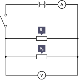
- Close the switch and record the voltmeter and ammeter readings once again.
- Calculate the total resistance of both resistors in parallel using:
:::
Results:
| Resistor | Potential Difference / V | Current / A | Resistance / Ω\OmegaΩ |
|---|---|---|---|
| R1 | 4.00 | 0.40 | 10 |
| R2 | 4.00 | 0.40 | 10 |
| In series | 4.00 | 0.20 | 20 |
| In parallel | 4.00 | 0.80 | 5 |
infoNote
Analysis:
- Series Circuit: The total resistance of two resistors in series is the sum of their individual resistances:
In this case, the two 10 Ω resistors in series give a total resistance of 20 Ω.
- Parallel Circuit: The total resistance of two resistors in parallel is less than the resistance of either resistor. It is calculated using the formula:
For two 10 resistors in parallel, the total resistance is 5 Ω.
Evaluation:
- Series Circuit: In series, the resistance is higher because there is only one path for the electrons to flow. The current must pass through both resistors, which doubles the resistance compared to using just one resistor.
- Parallel Circuit: In parallel, the resistance is reduced because the current has more than one path to flow through. This effectively halves the resistance, as the current can split between the two resistors.
infoNote
The experiment can also be conducted using filament lamps instead of resistors. Filament lamps behave similarly to resistors in series and parallel circuits, though their resistance increases as the temperature of the filament increases.
Hazards and Control Measures:
| Hazard | Consequence | Control Measures |
|---|---|---|
| Heating of wires and resistors | Minor burns | Ensure the circuit is set up before closing the switch to avoid excessive heating. |