Lenses & ray diagrams (Edexcel GCSE Physics Combined Science): Revision Notes
Lenses & ray diagrams
Lenses
Lenses change images by refracting light. Ray diagrams are used to represent the path of light through lenses and can be used to show how images are formed through a lens. Lenses can be either concave or convex.
Convex/Converging Lenses
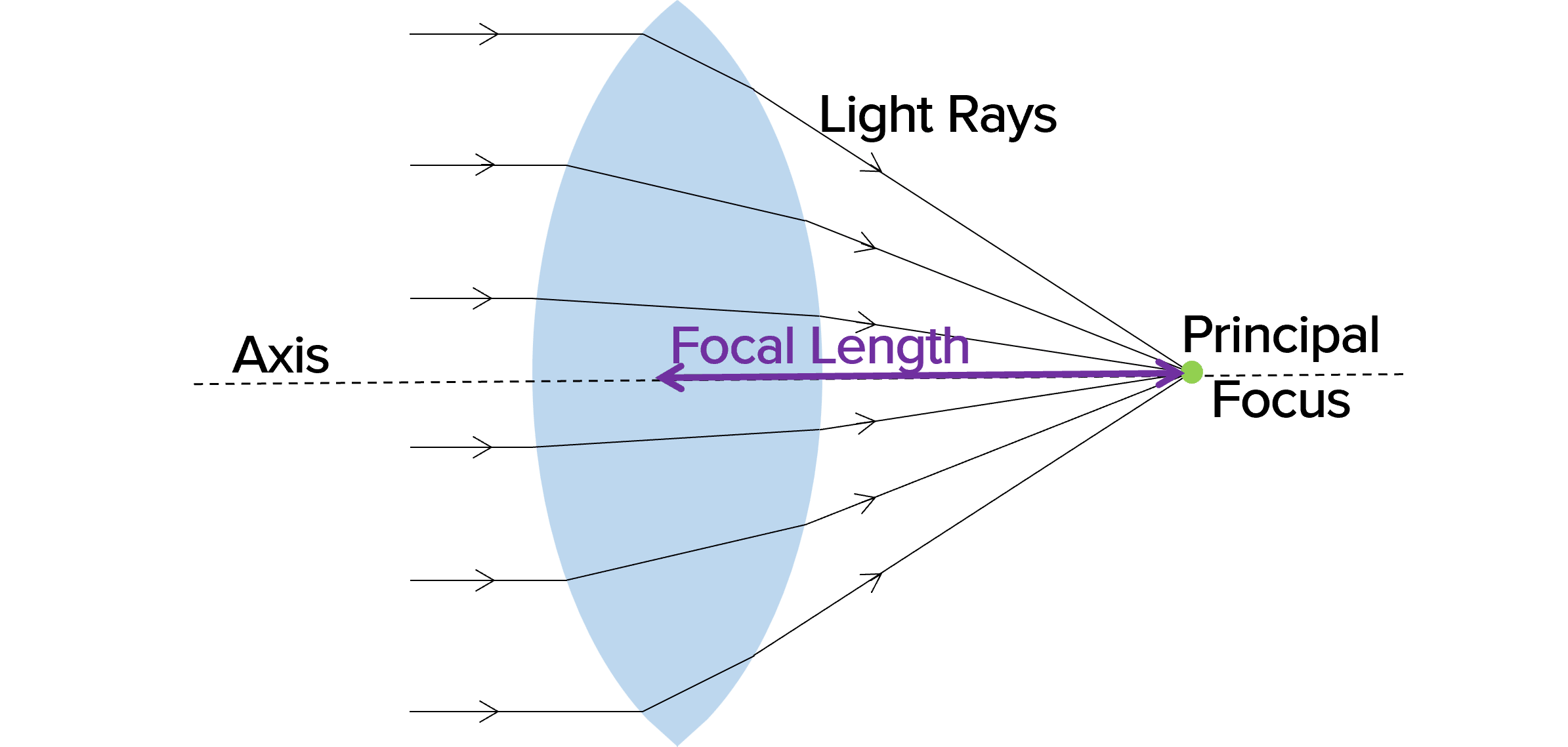
Convex lenses are thicker in the middle than at the edges. Light entering the convex lens is refracted inwards towards a point called the principal focus. There is a principal focus on either side of the lens, for rays entering the lens from each direction. The distance between the centre of the lens to the principal focus is called the focal length. The ray diagram below shows the effect of a convex lens on the path of light rays.
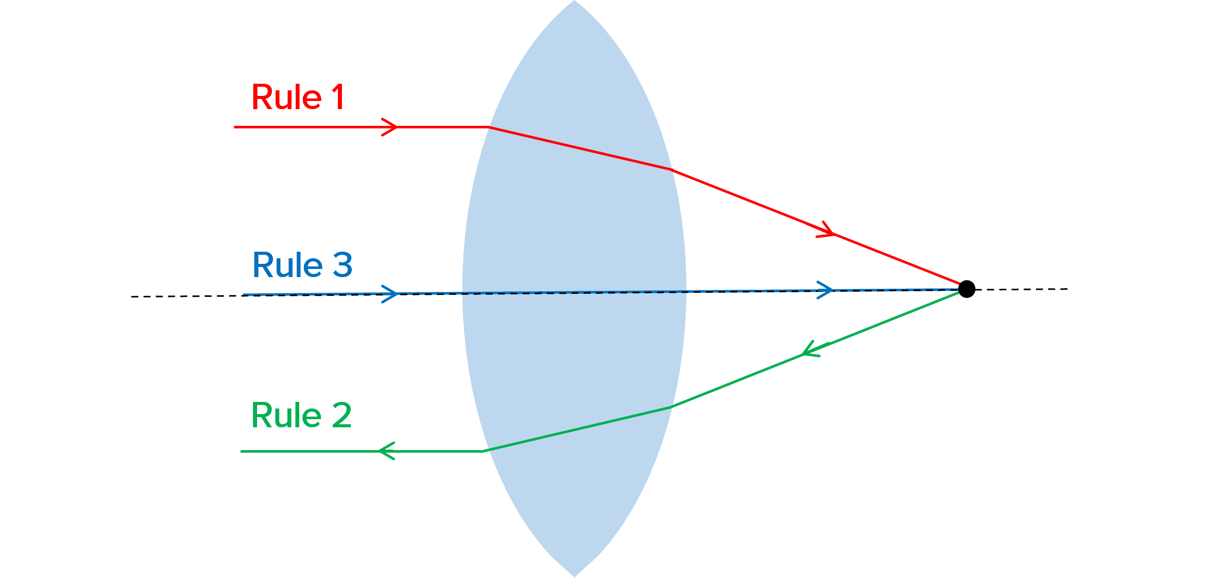
You need to remember the following rules about convex lenses:
- Rule 1: Any ray that enters the lens parallel to the axis will refract through the lens and pass through the principal focus.
- Rule 2: Any ray that enters the lens from the principal focus will refract through the lens and leave the lens parallel to the axis.
- Rule 3: Any ray that enters the lens along the axis will continue in the same direction.
Concave/Diverging Lenses
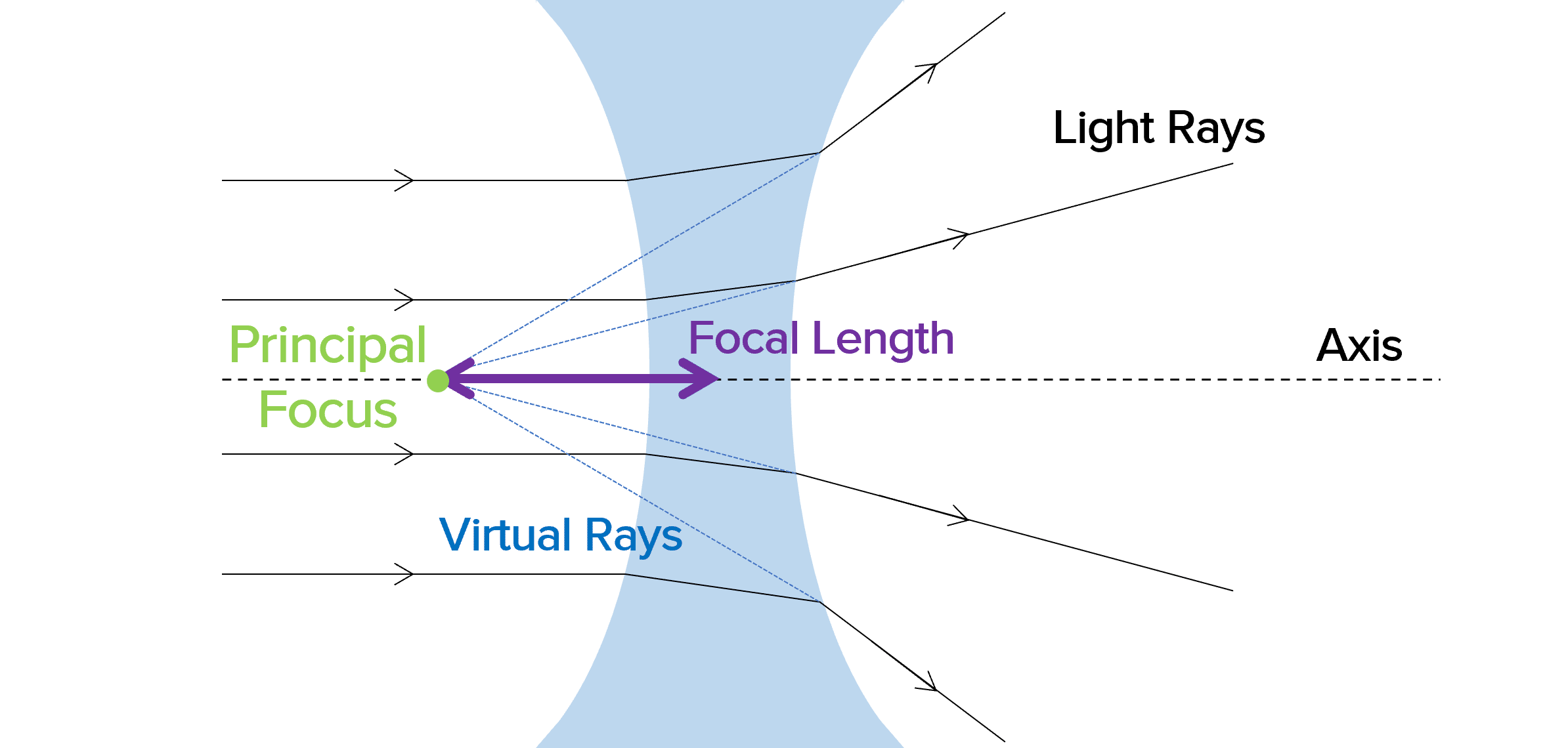
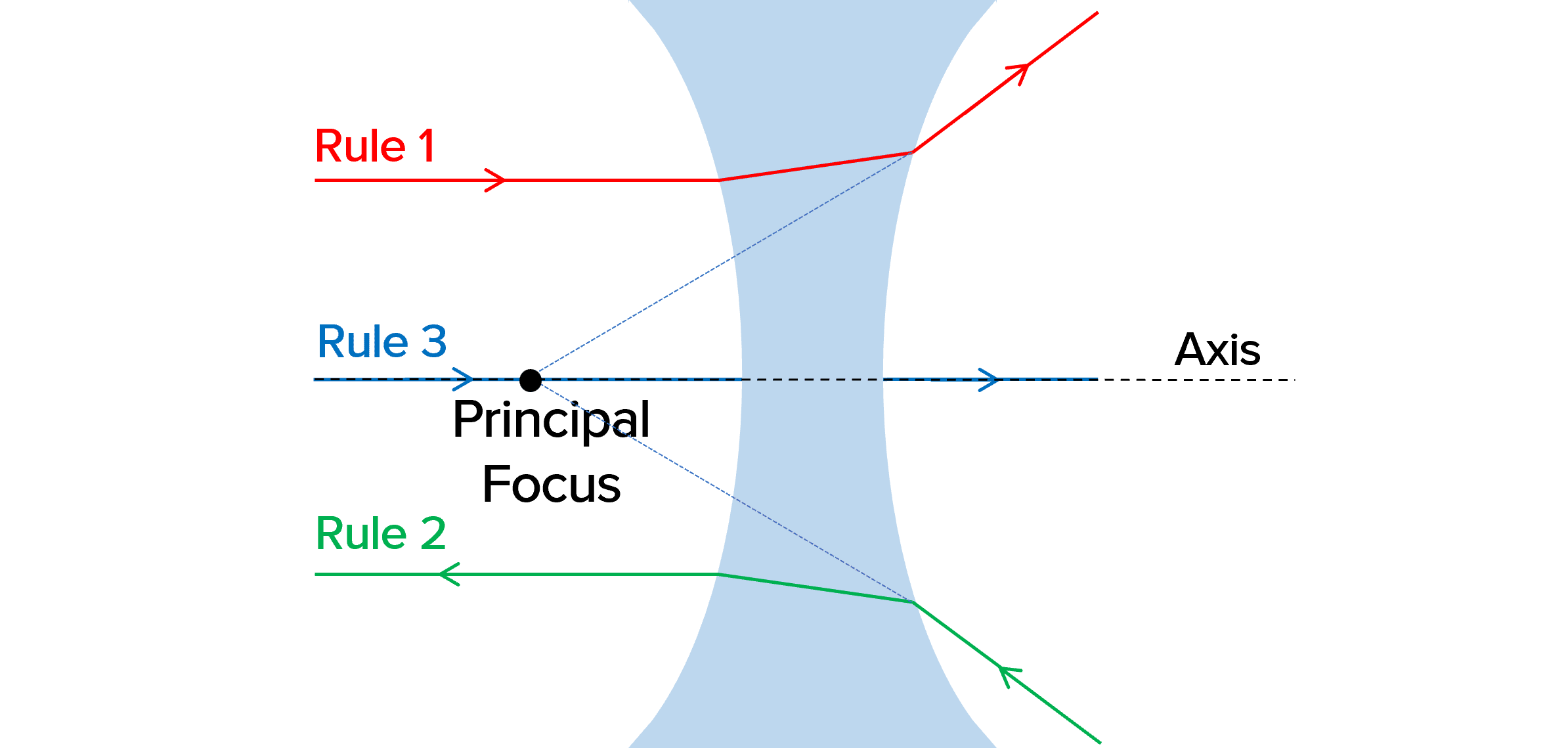
Concave/diverging lenses are thicker at the edges and thinner in the centre. They cause light to diverge, meaning it spreads out. The principal focus of a concave lens is the point where rays hitting the lens parallel to the axis appear to have come from. We represent this on a ray diagram by tracing virtual rays backwards from the ray leaving the lens. Like a convex lens, there is a principal focus on both sides of the lens.
There are also rules to remember for concave lenses:
- Rule 1: Any ray that enters the lens parallel to the axis will refract through the lens and travel in line with the principal focus so that it appears to have come from the principal focus.
- Rule 2: Any ray that enters the lens, travelling towards the principal focus refracts through the lens and leaves it parallel to the axis.
- Rule 3: Any ray that enters the lens along the axis continues in the same direction.
Real and Virtual Images
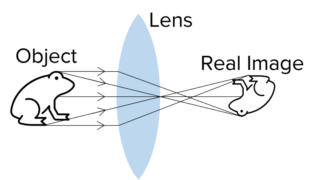
When light comes together to form an image, such as on a screen or on the retina (the back of the eye), a real image is formed.
Only convex/converging lenses produce real images.
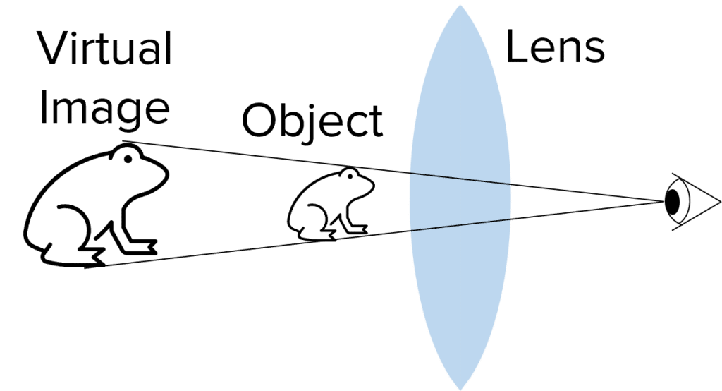
A virtual image is formed when light rays diverge, and so the object appears to be in a different place. For example, when you look into a mirror, you see a virtual image. This is because the reflexion appears to be behind the mirror.
Concave lenses always produce virtual images. Convex lenses may also produce virtual images.
Drawing ray diagrams
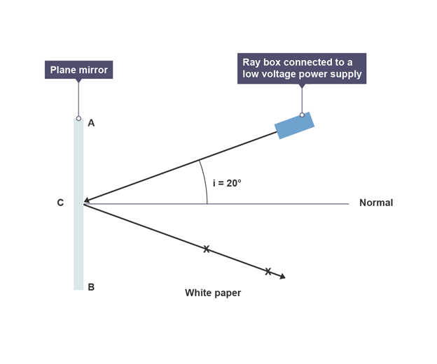
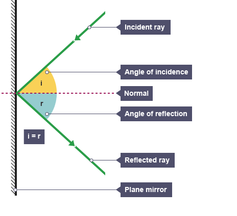
Ray diagrams show the path a wave takes when it crosses from one material to another. They help to visualise how light or other waves change direction when entering a different medium.\
Key Components:
- Boundary: The line separating two different materials (e.g., air and glass).
- Normal: An imaginary line drawn perpendicular (90 degrees) to the boundary.
- Incident Ray: The ray of light (or wave) that hits the boundary.
- Angle of Incidence: The angle between the incident ray and the normal.
- Refracted Ray: The ray that bends and travels in the second material after crossing the boundary.
- Angle of Refraction: The angle between the refracted ray and the normal.
Steps to draw a Ray Diagram:
- Draw the Boundary: Start by drawing a straight line to represent the boundary between two materials (e.g., air and glass).
- Draw the Normal: Draw a dashed line at 90 degrees to the boundary. This is the normal, which is used to measure angles.
- Incident Ray: Draw a ray approaching the boundary from one side. This ray should meet the normal at the point where it crosses the boundary.
- Angle of Incidence: Measure the angle between the incident ray and the normal. This is called the angle of incidence.
- Refracted Ray:
- If the second material is more optically dense (e.g., air to glass), the refracted ray bends towards the normal, making the angle of refraction smaller than the angle of incidence.
- If the second material is less optically dense (e.g., glass to air), the refracted ray bends away from the normal, making the angle of refraction larger than the angle of incidence.
Important Points:
- Optical Density: Denser materials slow down waves more, causing them to bend towards the normal. Less dense materials speed up waves, causing them to bend away from the normal.
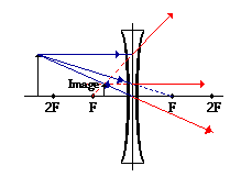
Draw a ray diagram for an image through a diverging lens
- Pick a point on the top of the object. Draw a ray going from the object at the lens parallel to the axis of the lens
- Draw another ray from the top of the object going right through the middle of the lens
- The incident ray that's parallel to the axis is refracted so appears to come from the principal focus (F). Draw a ray from the principal focus making it dotted before it reaches the lens – virtual
- The ray passing through the middle of the lens doesn't bend
- Mark where this ray meets the virtual ray which is the top of the image.
- Repeat to get a point for the bottom of object
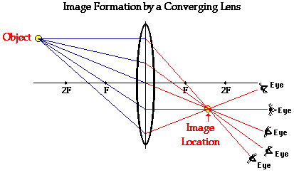
Draw a ray diagram for an image through a converging lens
- Pick a point on the top of the object. Draw a ray going from the object to the lens parallel to the axis of the lens
- Draw another ray from the top of the object going right through the middle of the lens
- The incident ray that's parallel to the axis is refracted through the principal focus (F). Draw a refracted ray passing through F.
- The ray passing through the middle of the lens doesn't bend
- Mark where the rays meet which is the top of the image
- Repeat to get bottom of object