Processes (AQA GCSE Design and Technology): Revision Notes
Electronic systems - Processes
Electronic systems form the backbone of modern technology, from simple circuits to complex devices. Understanding the key processes involved in electronic systems is essential for working with new and emerging technologies.
What are microcontrollers?
A microcontroller is essentially a tiny computer built onto a single chip that can process information within an electronic circuit. Think of it as the "brain" of an electronic system that can make decisions and control other components based on the instructions it receives.
 These remarkable components work by running programmes that tell them exactly what to do. The programming can be done using machine code, which uses binary numbers (0s and 1s), but in educational settings, a simpler programming language called BASIC is commonly used to make learning easier.
The process of programming a microcontroller involves writing instructions on a computer and then transferring this programme to the microcontroller chip. Once programmed, the microcontroller can operate independently to control various outputs like motors, lights, or sensors based on the inputs it receives.

PICs (Programmable interface controllers)
PICs represent a special type of microcontroller that offers exceptional versatility in electronic projects. These components can be programmed to perform various functions such as counting events, controlling timing sequences, or making logical decisions within a circuit.
What makes PICs particularly valuable is their flexibility and cost-effectiveness. They can be found in numerous everyday products including cars, washing machines, remote controls, and microwave ovens. This widespread use demonstrates their reliability and adaptability to different applications.
One significant advantage of using PICs is their ability to reduce the physical size of electronic circuits while simultaneously increasing functionality. Rather than using multiple separate components, a single PIC can often replace several traditional integrated circuits, making devices more compact and efficient.
Understanding timers in electronic systems
Timing control plays a crucial role in many electronic applications, and integrated circuits designed specifically for timing functions help achieve precise control over when events occur in a circuit.
There are two main types of timing outputs that these circuits can produce:
Monostable devices create a single pulse output that can be either in an "on" or "off" state. These are particularly useful for applications like alarm sensors that need to operate an audible warning once a sensor detects something, such as movement or temperature changes.
Astable devices generate an oscillating output that continuously alternates between "on" and "off" states. This makes them perfect for applications requiring flashing lights, such as warning signals or alarm system indicators.
Specialised counting circuits, like the 4026 decade counter, can work alongside timers to count the number of pulses generated. This functionality proves useful in applications ranging from digital clocks to pressure-sensitive devices that need to track the number of activations.
Practical Application: Traffic Light System
A traffic light system uses astable timers to control the timing sequence:
- Red light: 30 seconds (monostable timer)
- Green light: 25 seconds (monostable timer)
- Yellow light: 5 seconds (monostable timer)
The astable circuit coordinates the entire sequence, ensuring continuous operation.
Decision making through logic gates
Logic gates serve as the fundamental decision-making components in electronic circuits. These components analyse input signals and produce specific outputs based on predetermined logical rules.
 Most logic gates work with two input signals and generate a single output signal. The three primary types of logic gates each follow different logical rules:
AND gates require both input signals to be active (high) before producing an active output. Think of this like a security system that needs both a key card AND a PIN code to grant access.
OR gates will produce an active output when either one input OR the other input (or both) is active. This is similar to a doorbell system where pressing either the front door button OR the back door button will ring the bell.
NOT gates work differently by inverting whatever input they receive. If the input is active, the output becomes inactive, and vice versa. This is like a switch that turns a light off when you want it on, and on when you want it off.
Truth tables and binary logic
Truth tables provide a systematic way to understand how logic gates behave under all possible input conditions. These tables use binary notation where "0" represents a low or inactive signal, and "1" represents a high or active signal.
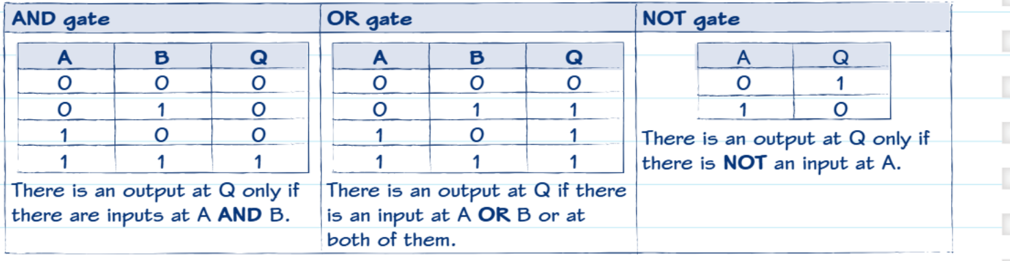 For AND gates, the output is only "1" when both inputs are "1". In all other combinations (0,0), (0,1), or (1,0), the output remains "0". This reinforces the concept that ALL inputs must be active for the gate to produce an active output.
OR gates show a different pattern where the output becomes "1" whenever at least one input is "1". Only when both inputs are "0" does the output remain "0". This demonstrates the "one or more" principle of OR logic.
Reading a Truth Table: AND Gate
| Input A | Input B | Output |
|---|---|---|
| 0 | 0 | 0 |
| 0 | 1 | 0 |
| 1 | 0 | 0 |
| 1 | 1 | 1 |
Only when both inputs are "1" does the AND gate produce a "1" output.
NOT gates have the simplest truth table since they only have one input. When the input is "0", the output is "1", and when the input is "1", the output is "0". This consistent inversion makes NOT gates useful for creating opposite signals when needed.
Understanding these truth tables is essential because they show exactly how electronic systems will behave in every possible situation, allowing designers to predict and control circuit behaviour precisely.
Remember!
Key Points to Remember:
-
Microcontrollers are single-chip computers that can be programmed to control electronic circuits and make decisions based on inputs they receive.
-
PICs offer flexibility and cost-effectiveness for a wide range of applications, from household appliances to automotive systems, while reducing circuit complexity.
-
Timing circuits come in two main types: monostable (single pulse) for one-time events and astable (oscillating) for continuous switching applications.
-
Logic gates make binary decisions using AND (all inputs must be high), OR (any input can be high), and NOT (inverts the input) operations.
-
Truth tables map out all possible combinations of inputs and outputs, providing a complete picture of how logic gates behave in every situation.