Pulleys and belts (AQA GCSE Design and Technology): Revision Notes
Pulleys and belts
What are pulleys and belts?
Pulleys and belts work together as a mechanical system to transfer rotary motion from one shaft to another. This system allows power to be transmitted between different parts of a machine, making it essential in many engineering applications.
 A pulley consists of a wheel that has a specially shaped groove around its circumference. When a belt sits in this groove, the two components can work together effectively. The belt connects two separate pulleys, and as one pulley rotates, friction between the belt and groove causes the second pulley to rotate as well.
The pulley and belt system is one of the most fundamental mechanical power transmission methods used in engineering. From simple machines to complex industrial equipment, this principle enables efficient transfer of rotary motion across different parts of mechanical systems.
Understanding pulley systems
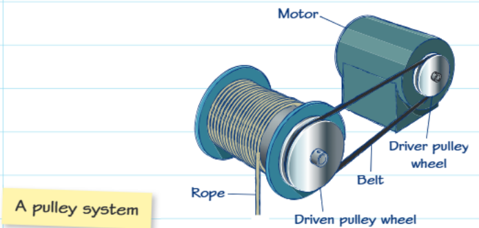
In any pulley system, you'll find two main components working together. The first pulley receives power from a motor or other power source - this is called the driver pulley wheel. The second pulley, known as the driven pulley wheel, receives the transferred motion and can then power other parts of the machine.
The system operates through friction between the belt and the grooved surfaces of both pulleys. As the driver pulley rotates, it grips the belt and moves it along. This belt movement then causes the driven pulley to rotate, successfully transferring the motion from one shaft to another.
Key Function: The driver pulley is always the input (receives power), while the driven pulley is always the output (delivers power to the next component in the system).
Types of belts and their characteristics
Different types of belts are available for various applications, each with specific advantages:
Round belts are highly efficient and versatile. They can be crossed over to change the direction of rotation, making them useful when you need the driven pulley to rotate opposite to the driver pulley.
V-belts have a wedge-shaped cross-section that reduces slippage by fitting snugly into corresponding V-shaped grooves in the pulley wheels. This design provides better grip and more reliable power transmission.
Flat belts offer excellent grip when operating at high speeds due to their large contact surface area with the pulley. Like round belts, they can also be crossed to reverse rotation direction.
Toothed belts feature teeth that mesh with corresponding grooves in the pulley wheels, eliminating slippage entirely. However, this design can create safety hazards if objects become trapped between the teeth and pulley.
Safety Warning: Toothed belts pose significant safety risks because objects can become trapped between the teeth and pulley grooves. Always ensure proper guarding and safety measures are in place when working with toothed belt systems.
Mathematical relationships in pulley systems
Understanding the mathematical relationships in pulley systems helps predict how changes in pulley size affect system performance.
Velocity ratio calculation
The velocity ratio determines how the sizes of the two pulleys relate to each other:
This ratio tells you how many times the driven pulley will rotate for each rotation of the driver pulley.
Essential Formula: The velocity ratio is crucial for understanding pulley system behaviour. A ratio less than 1 means speed increases, while a ratio greater than 1 means speed decreases.
Output speed calculation
Once you know the velocity ratio, you can calculate the actual output speed:
Where speeds are typically measured in revolutions per minute (RPM).
Worked example
Worked Example: Calculating Pulley System Output
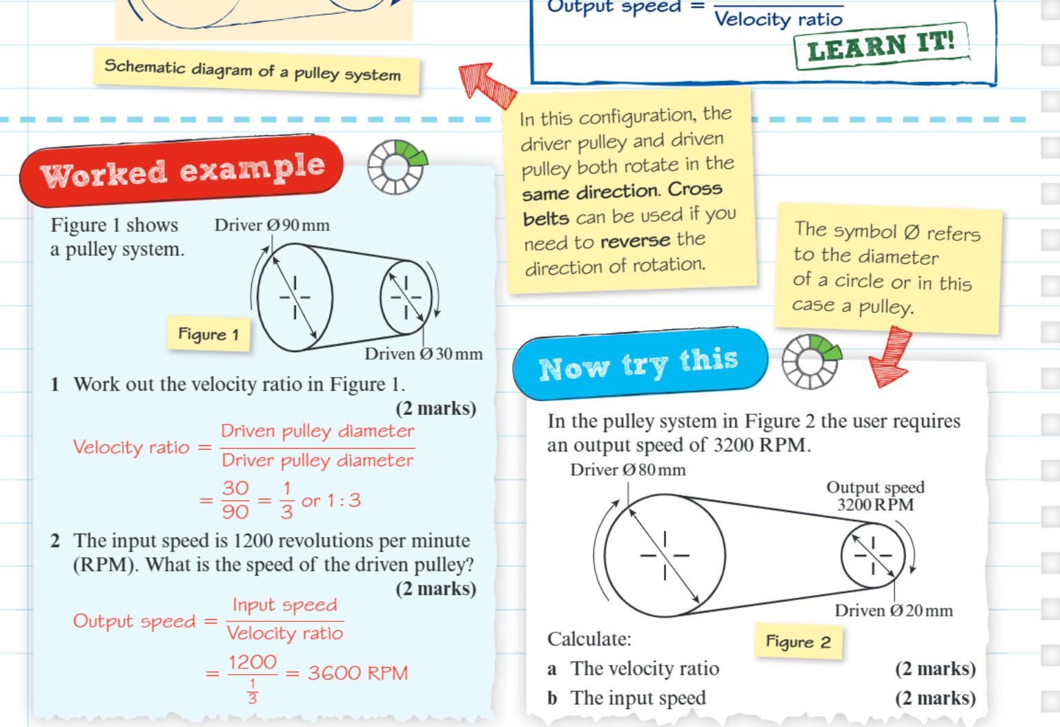
Consider a pulley system where the driver pulley has a diameter of 90mm and the driven pulley has a diameter of 30mm. The input speed is 1200 RPM.
Step 1: Calculate the velocity ratio
Step 2: Find the output speed
Result: The driven pulley rotates three times faster than the driver pulley.
This example shows that when the driven pulley is smaller than the driver pulley, the output speed increases. The driven pulley rotates three times faster than the driver pulley.
Direction of rotation considerations
In most pulley configurations, both pulleys rotate in the same direction when connected by a straight belt. However, crossing the belt can reverse the direction of rotation of the driven pulley. This technique is useful when you need the output shaft to rotate opposite to the input shaft.
The symbol represents diameter in technical drawings and calculations, which is important to recognise when working with pulley specifications.
Key Points to Remember:
- Pulleys and belts transfer rotary motion between shafts using friction
- The velocity ratio equals the driven pulley diameter divided by the driver pulley diameter
- Smaller driven pulleys create higher output speeds, while larger driven pulleys create lower output speeds
- Different belt types (round, V-belt, flat, toothed) offer different advantages for specific applications
- Crossing belts can reverse the direction of rotation between driver and driven pulleys