17.1 – Measuring the Wavelength of Light (Leaving Cert Physics): Revision Notes
17.1 – Measuring the Wavelength of Light
Introduction
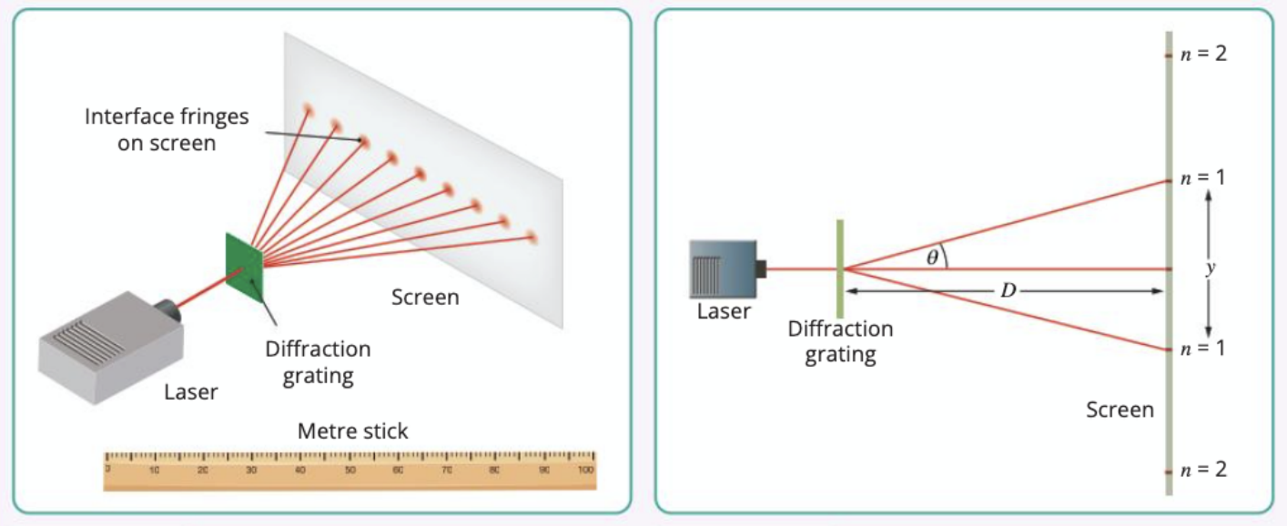
This experiment uses a diffraction grating to measure the wavelength of monochromatic light from a laser. When light passes through a diffraction grating, it creates a series of bright and dark interference fringes on a screen. By measuring the positions of these fringes and using the known properties of the grating, we can calculate the wavelength of the light.
The principle relies on the wave nature of light and how it diffracts when passing through the regularly spaced slits in the grating.
This experiment provides direct evidence for the wave nature of light through the observation of interference patterns. The regular spacing of the diffraction grating acts as multiple coherent light sources, creating the characteristic pattern of bright and dark fringes.
Equipment needed
- Diffraction grating with known grating constant
- Laser (monochromatic light source)
- Metre stick or ruler
- Screen (such as a wall or white card)
- Grating holder
- Safety equipment
The grating constant (d) is the spacing between adjacent slits in the diffraction grating, typically expressed as the number of lines per millimetre. This value is crucial for calculating the wavelength and should be recorded accurately.
Safety considerations
⚠️ LASER SAFETY WARNING: Laser light is hazardous to the eyes. Never look directly at the laser beam or at reflections of it. If laser light enters your eyes, immediately close them and look away. Always handle lasers with extreme care.
Experimental setup
The apparatus consists of three main components arranged in a straight line:
- Laser: Provides monochromatic light
- Diffraction grating: Splits the light into different orders
- Screen: Shows the interference pattern
The laser shines through the diffraction grating, creating a central bright spot and several diffracted images on either side.
Proper alignment is crucial for accurate results. The laser beam should be perpendicular to the grating, and the grating should be parallel to the screen. Any misalignment will introduce systematic errors in your measurements.
Method
Setting up the equipment
The setup process requires careful attention to alignment and positioning to ensure accurate measurements.
- Set up the equipment as shown in the diagram, with the laser, diffraction grating, and screen arranged in a straight line
- Use a distance D between the grating and screen of 1-3 metres (the larger the distance, the better the accuracy)
- Ensure that:
- The grating and screen are vertical and parallel to each other
- The lines of the grating are vertical
- The grating is perpendicular to the light from the laser
Critical Alignment Check: The larger the distance D, the more accurate your results will be. This is because measurement errors in Y become a smaller percentage of the total when D is large, reducing the overall uncertainty in your wavelength calculation.
Taking measurements
The measurement process involves systematically recording the positions of diffracted images for different orders.
- Turn on the laser and adjust the equipment until the row of images on the screen is horizontal
- Use the metre stick to carefully measure the distance D between the diffraction grating and the screen
- Locate the first order diffracted images on each side of the central bright spot
- Measure the distance Y between the centres of both first order images and record this value
- Repeat steps 6 and 7 for the second and third order diffracted images
- Find the grating constant d from the information provided with the grating
- Complete the data table and calculate the wavelength for each order
Avoiding Parallax Error: When measuring distances, avoid the error of parallax by viewing the scale directly from above. This ensures that your eye is aligned perpendicular to the measurement scale, giving the most accurate reading.
Data collection and calculations
| Order of Image (n) | Distance between centres of corresponding images (Y) | Y/2 | tan θ = Y/(2D) | sin θ | Wavelength λ (m) = d sin θ/n |
|---|---|---|---|---|---|
| 1 | |||||
| 2 | |||||
| 3 |
Key formula
The fundamental relationship for this experiment is the diffraction grating equation. The wavelength is calculated using:
Where:
- λ = wavelength of light (m)
- d = grating constant (spacing between slits) (m)
- θ = diffraction angle
- n = order of diffraction (1, 2, 3, etc.)
Calculating the angle
The diffraction angle θ can be found using trigonometry. For small angles, we use:
Where:
- Y = distance between corresponding images on opposite sides
- D = distance from grating to screen
Worked Example: Calculating Wavelength
Given data:
- Grating constant: d = 3.33 × 10⁻⁶ m (300 lines per mm)
- Distance to screen: D = 2.0 m
- Distance between first order images: Y = 0.78 m
Step 1: Calculate the diffraction angle tan θ = Y/(2D) = 0.78/(2 × 2.0) = 0.195 θ = tan⁻¹(0.195) = 11.0°
Step 2: Calculate wavelength using the grating equation λ = d sin θ/n = (3.33 × 10⁻⁶ × sin 11.0°)/1 λ = 3.33 × 10⁻⁶ × 0.191 = 6.36 × 10⁻⁷ m = 636 nm
This corresponds to red light, which matches our expectation for a red laser.
Sources of error
Several factors can affect the accuracy of your results and understanding these helps improve experimental technique:
- Grating alignment: The grating may not be exactly at right angles to the light from the laser, leading to systematic errors in angle measurement
- Screen position: The grating may not be perfectly parallel to the screen, causing geometric distortions in the diffraction pattern
- Measurement errors: When measuring distances, avoid the error of parallax by viewing the scale directly from above
- Grating quality: If D is large and the diffraction grating has many lines per millimetre (e.g., 600), Y will be large, reducing percentage errors in measuring D and Y for a more accurate wavelength value
Improving Accuracy: The most effective way to improve accuracy is to increase the distance D between the grating and screen. This makes the diffracted images spread out more, making them easier to measure precisely and reducing the relative impact of measurement uncertainties.
Worked example
Here's how to determine the expected results for a common experimental setup:
Worked Example: Expected Results for Red Laser
If you're using a grating with 300 lines per mm:
- Grating constant d = 1/(300 × 1000) = 3.33 × 10⁻⁶ m
- For a typical red laser with λ ≈ 650 nm, you should expect to see clear diffraction patterns
Expected first order angle: sin θ = nλ/d = (1 × 650 × 10⁻⁹)/(3.33 × 10⁻⁶) = 0.195 θ = 11.2°
For a screen distance of D = 2.0 m: Y = 2D tan θ = 2 × 2.0 × tan(11.2°) = 0.79 m
This gives you a reference point to check if your experimental setup is working correctly.
Exam tips
Understanding the key concepts and common exam approaches will help you succeed in assessments:
Essential Exam Strategies:
- Always show your working when calculating wavelengths - marks are awarded for method as well as final answers
- Remember to convert units appropriately (mm to m, nm to m, etc.) - unit errors are common
- State the formula before substituting values - this demonstrates understanding of the physics
- Include appropriate significant figures in your final answer based on your measurement precision
- Be able to explain why larger distances D improve accuracy - this tests your understanding of experimental design
Summary
This experiment demonstrates fundamental wave optics principles and provides hands-on experience with precision measurement techniques.
Key Points to Remember:
- Safety first: Never look directly at laser light - it can permanently damage your eyes
- The key formula: λ = d sin θ / n relates wavelength to grating constant, diffraction angle, and order
- Accuracy improves: with larger distances between grating and screen, and with gratings having more lines per millimetre
- Multiple measurements: Taking readings for different orders (n = 1, 2, 3) and averaging gives more reliable results
- This experiment demonstrates: the wave nature of light through interference and diffraction effects