22.3 – Investigating the Effect of Temperature on Resistance (Leaving Cert Physics): Revision Notes
22.3 – Investigating the Effect of Temperature on Resistance
Understanding how temperature affects electrical resistance is crucial in physics and electronics. Different materials respond to temperature changes in distinctly different ways, and these experiments help us explore these relationships practically.
What we're investigating
These experiments examine how the electrical resistance of different materials changes when we alter their temperature. We'll look at two main types of materials:
- Metallic conductors (like copper wire)
- Thermistors (temperature-sensitive semiconductor devices)
Key Discovery
These materials behave in completely opposite ways when heated! This fundamental difference makes them useful for different applications in electronics and temperature measurement.
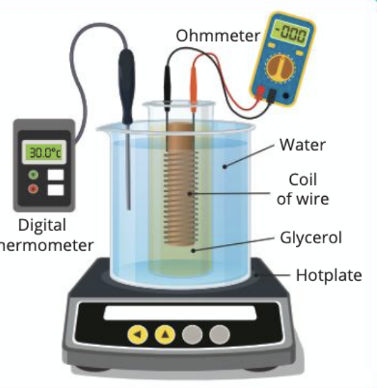
Student experiment 22.3(A): Metallic conductor investigation
Equipment needed
You'll need several pieces of apparatus to carry out this investigation safely and accurately:
- Wire coil (copper works well)
- Digital thermometer (reading from 0°C to 100°C)
- Ohmmeter or digital multimeter
- Hotplate for controlled heating
- Large test tube or beaker (500 ml capacity)
- Liquid paraffin or glycerol
- Retort stand and clamp for support
Method and procedure
The experimental technique requires careful attention to detail for accurate results:
-
Initial setup: Connect your ohmmeter to determine the wire coil's resistance at room temperature. Select an appropriate resistance range on your metre for the entire experiment.
-
Check connections: Ensure the ohmmeter probes connect firmly to the coil terminals. Any loose connections will introduce measurement errors that must be avoided.
-
Prepare heating apparatus: Secure the coil firmly to prevent movement during heating. This keeps your electrical connections stable throughout the experiment.
-
Begin heating: Place cold tap water in your beaker and position the equipment as shown in the diagram. Allow the coil and thermometer to reach thermal equilibrium before taking initial readings.
-
Record initial values: When the thermometer shows a steady reading, measure and record both the coil's temperature and resistance simultaneously.
-
Heat gradually: Switch on the hotplate and heat the water slowly. When the glycerol temperature rises by approximately 5°C, take new measurements of both temperature and resistance.
-
Continue measurements: Keep heating gently, taking readings every 5°C until you reach nearly 100°C.
Safety Warning
Keep the ohmmeter and connecting wires well away from the hotplate to prevent damage or electrical hazards.
Data collection
| Temperature of coil θ (°C) | Resistance of coil R (Ω) |
|---|---|
Expected results
When you plot your data on a graph, you should observe a clear linear relationship between temperature and resistance. The graph will show resistance increasing steadily as temperature rises.
This demonstrates that metallic conductors have a positive temperature coefficient - their resistance increases proportionally with temperature.
Sources of experimental error
Common Sources of Error
Several factors can affect your results:
- Rapid heating: If you heat too quickly, the coil temperature changes faster than you can read it, making accurate measurements difficult
- Non-uniform temperature: Stir the liquid continuously so it maintains a uniform temperature throughout
- Poor thermal contact: The coil must be fully immersed in the heated liquid for accurate temperature measurement
- Sensitive thermometer: Use a digital thermometer with high precision and low heat capacity for best results
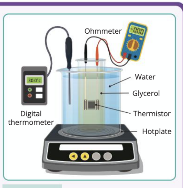
Student experiment 22.3(B): Thermistor investigation
Equipment needed
This experiment uses similar apparatus with one key difference:
- Thermistor (replaces the wire coil)
- Digital thermometer (0°C to 100°C range)
- Ohmmeter or digital multimeter
- Hotplate for temperature control
- Beaker (500 ml)
- Liquid paraffin or glycerol
- Retort stand and clamp
Method and procedure
The experimental approach mirrors the previous investigation:
-
Initial resistance measurement: Connect the ohmmeter to your thermistor and determine its room temperature resistance. You may need to adjust the resistance range during the experiment as values change significantly.
-
Secure connections: Ensure all electrical connections remain firm throughout the heating process to avoid systematic errors in your readings.
-
Setup heating system: Connect the thermometer probes securely to the thermistor for accurate temperature monitoring.
-
Establish thermal equilibrium: Place cold water in the beaker and allow both thermistor and thermometer to reach a stable temperature before recording initial values.
-
Begin gradual heating: Heat the thermistor and its surrounding medium slowly, recording both temperature and resistance values when the thermometer gives steady readings.
-
Continue heating carefully: Take measurements approximately every 5°C as you heat towards 100°C, maintaining the same careful approach throughout.
Safety Reminder
Keep electrical components away from the hotplate and ensure good thermal contact between the thermistor and heating medium.
Data collection
| Temperature of thermistor θ (°C) | Resistance of thermistor R (Ω) |
|---|---|
Expected results
Your thermistor results will look dramatically different from the metallic conductor. The graph shows resistance decreasing rapidly as temperature increases, creating a curved (exponential) relationship rather than a straight line.
This demonstrates that thermistors have a negative temperature coefficient - their resistance decreases significantly as temperature rises.
Sources of experimental error
Precautions for Thermistor Experiments
Similar precautions apply to the thermistor experiment:
- Slow, controlled heating: Heat gradually to allow accurate temperature and resistance measurements
- Uniform temperature: Ensure the liquid medium has consistent temperature throughout
- Sensitive equipment: Use precise digital measuring instruments for better accuracy
- Proper thermal contact: The thermistor should be fully immersed in the heated medium
Key differences between materials
Understanding why these materials behave differently helps explain their practical applications:
Metallic conductors (like copper wire):
- Resistance increases linearly with temperature
- Atoms vibrate more at higher temperatures, impeding electron flow
- Used in applications where predictable resistance changes are needed
Thermistors:
- Resistance decreases exponentially with higher temperatures
- Semiconductor material allows more current flow when heated
- Used as temperature sensors because of their high sensitivity
Practical applications
These resistance-temperature relationships have important real-world uses:
Real-World Applications
- Temperature sensors: Thermistors provide accurate temperature measurements in digital thermometers and HVAC systems
- Temperature compensation: Understanding resistance changes helps design stable electronic circuits that work reliably across temperature ranges
- Safety devices: Some circuits use resistance changes to detect overheating and automatically shut down equipment
Remember!
Key Points to Remember:
-
Metallic conductors show increasing resistance with temperature - the relationship is linear and predictable
-
Thermistors demonstrate decreasing resistance with temperature - the relationship is exponential and highly sensitive
-
Careful experimental technique is essential - heat slowly, maintain good connections, and ensure uniform temperatures
-
Safety first - keep electrical equipment away from heat sources and ensure proper insulation
-
Both materials have practical applications - metals for predictable behaviour, thermistors for sensitive temperature detection