Levers (AQA GCSE Design and Technology): Revision Notes
Levers
Levers are simple machines that help us apply forces more effectively. They work by using a rigid bar that rotates around a fixed point to either multiply force or increase the distance and speed of movement. Understanding how levers work is essential for grasping many mechanical systems we use every day.
What is a lever?
A lever consists of three essential components that work together to create mechanical advantage. These components determine how the lever will behave and what type of work it can perform most effectively.
Understanding the relationship between these three components is crucial for analysing any lever system. The positioning of each component determines whether the lever will multiply force, increase speed, or provide precision control.
Parts of a lever
Every lever system contains exactly three parts:
- The effort - This is the input force that you apply to operate the lever. It's the force you put in to make the system work.
- The pivot (fulcrum) - This is the fixed point around which the lever rotates or balances. The position of this pivot determines the lever's characteristics.
- The load - This is the output force or resistance that the lever works against. It's what you're trying to move or overcome.
The relationship between these three components determines how effective the lever will be and what type of work it's best suited for.
Types of levers
Levers are classified into three different orders based on the arrangement of the effort, load, and pivot. Each order has distinct characteristics and is suited to different types of tasks.
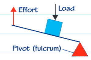
First order levers
In first order levers, the pivot sits between the effort and the load, placing them on opposite sides of the fulcrum. This arrangement is particularly useful when you need to lift heavy objects but can accept that your effort will need to move through a greater distance than the load.
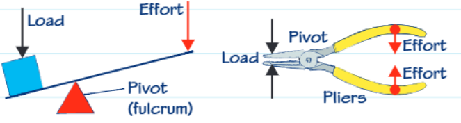 These levers are designed to help you lift greater loads, but there's a trade-off - your effort force must travel a longer distance than the load moves. Think of a crowbar or scissors as everyday examples of this type of lever system.
Common First Order Lever Examples:
- Crowbars and pry bars
- Scissors and pliers
- See-saws and balance scales
- Claw hammers (when removing nails)
Second order levers
Second order levers position both the load and effort on the same side of the pivot, with the load sitting between the pivot and the effort point. This configuration also helps lift greater loads while requiring the effort to move through a greater distance.
The key advantage of second order levers is that they provide good mechanical advantage while keeping the effort and load on the same side of the system. Wheelbarrows and nutcrackers are common examples of this lever type.
Third order levers
Third order levers place the effort between the pivot and the load. In this arrangement, the effort applied is actually greater than the load being moved. While this might seem inefficient, these levers are specifically designed for precision work where control and accuracy are more important than force multiplication.
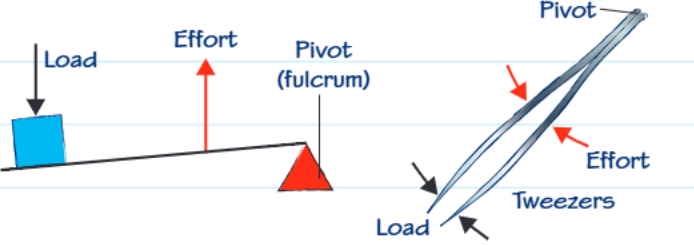 Examples like tweezers and fishing rods demonstrate how third order levers prioritise precision and fine control over raw mechanical advantage.
Key Distinction: Third order levers sacrifice force multiplication for speed and precision. They're not about making work easier - they're about making work more controlled and accurate.
Mechanical advantage
Mechanical advantage tells us how effectively a lever multiplies the input force. It's a crucial concept for understanding how much benefit you gain from using a particular lever system.
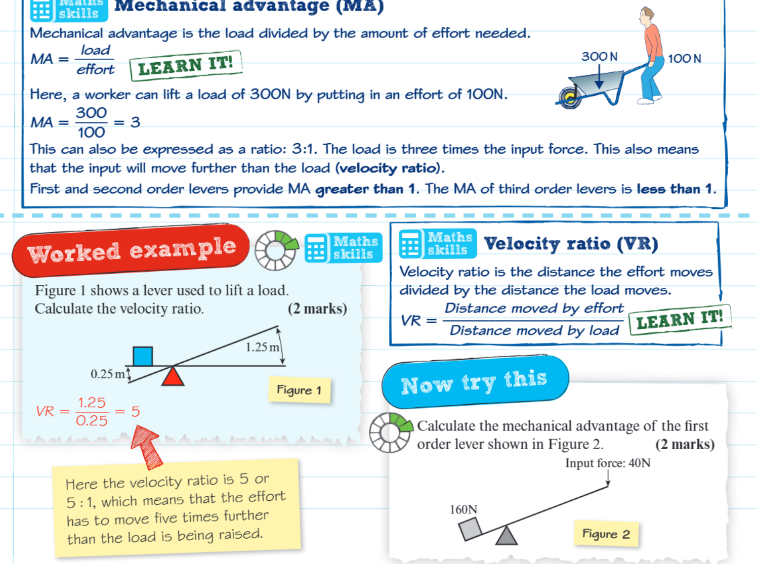 The mechanical advantage is calculated by dividing the load force by the effort force needed to move it. When the mechanical advantage is greater than 1, the lever is helping you by multiplying your input force. When it's less than 1, you're trading force for other benefits like speed or precision.
Worked Example: Calculating Mechanical Advantage
A crowbar is used to lift a 300N load with an applied effort of 100N.
Step 1: Identify the values
- Load force = 300N
- Effort force = 100N
Step 2: Apply the formula Mechanical Advantage = Load ÷ Effort = 300N ÷ 100N = 3
Step 3: Interpret the result This means the lever is tripling your input force, giving you a 3:1 mechanical advantage.
First and second order levers typically provide mechanical advantages greater than 1, making them excellent for heavy lifting tasks. Third order levers usually have mechanical advantages less than 1, but they excel in applications requiring fine control and precision.
Velocity ratio
Velocity ratio describes the relationship between the distances moved by the effort and load in a lever system. It's calculated by dividing the distance the effort moves by the distance the load moves.
This concept helps explain the fundamental trade-off that exists in lever systems. When you gain mechanical advantage (force multiplication), you typically sacrifice distance - your effort must move further than the load. Conversely, when you gain speed or distance advantage, you usually need to apply more force.
Understanding the Trade-off: In lever systems, you can't get something for nothing. If you gain force advantage, you lose distance advantage, and vice versa. This is a fundamental principle of all simple machines.
For instance, if your effort moves 5 times further than the load, the velocity ratio is 5:1. This means that while you might gain mechanical advantage, your effort point travels five times the distance of the load.
Lever balance principle
When a lever is perfectly balanced, there's a fundamental relationship between the forces and distances involved. The force multiplied by distance on one side of the pivot equals the force multiplied by distance on the other side.
The Lever Balance Equation:
This principle explains why longer lever arms provide greater mechanical advantage and why the position of the pivot is so crucial to a lever's effectiveness.
Practical applications
Understanding levers helps explain how many tools and machines work in the real world. From simple hand tools like pliers and scissors to complex machinery, lever principles are everywhere. Even parts of your body work as lever systems - your arm acts as a third order lever when you lift objects, with your elbow as the pivot.
When designing or choosing tools, engineers and users consider whether they need force multiplication, precision control, or speed enhancement, then select the appropriate lever type for the task.
Levers in Your Body:
- Your arm: Third order lever (elbow = pivot, bicep = effort, hand = load)
- Your jaw: Third order lever for precise biting and chewing
- Your leg: Third order lever when kicking (hip = pivot, muscles = effort, foot = load)
Key Points to Remember:
- Levers have three essential parts: effort (input), load (output), and pivot (fulcrum)
- First and second order levers multiply force but require greater effort distance
- Third order levers provide precision and control rather than force multiplication
- Mechanical advantage shows how much force is multiplied (load ÷ effort)
- When you gain force advantage, you typically sacrifice distance and speed
- The lever balance principle: Force × Distance must be equal on both sides of the pivot