Specialist gears (AQA GCSE Design and Technology): Revision Notes
Specialist gears
When studying new and emerging technologies, it's important to understand different types of gear systems beyond simple spur gears. Specialist gears serve unique purposes and are designed to solve specific mechanical problems in various applications.
Bevel gears
Bevel gears are designed to transmit rotary motion through a 90-degree angle. Unlike standard gears that operate on parallel shafts, bevel gears work with shafts that intersect at right angles, making them perfect for changing the direction of motion in mechanical systems.
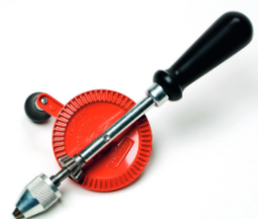 The key feature of bevel gears is their conical shape, which allows the teeth to mesh properly when the gear shafts are positioned at 90 degrees to each other. You'll commonly find bevel gears in hand drills and car differentials, where they help redirect power flow efficiently.
When bevel gears have the same number of teeth, they're called mitre gears. These special bevel gears maintain the same rotational speed while changing direction - the input and output speeds remain equal even though the motion turns through 90 degrees.
For velocity ratio calculations with bevel gears, you use the same formula as with standard spur gears. The velocity ratio equals the number of teeth on the driven gear divided by the number of teeth on the driver gear:
Worm and worm wheel systems
A worm and worm wheel system creates significant speed reductions while providing excellent mechanical advantage. The worm (which looks like a screw thread) meshes with the worm wheel to produce large reductions in rotational speed.
The unique characteristic of worm gear systems is that the worm acts as the driver and typically has only one tooth. This means that one complete revolution of the worm moves the worm wheel forwards by just one tooth, creating substantial speed reduction ratios.
These systems are particularly valuable in applications requiring security features, such as security gates and winch mechanisms. The worm and worm wheel arrangement naturally prevents load fallback - the system locks in position when the input stops turning, providing built-in safety.
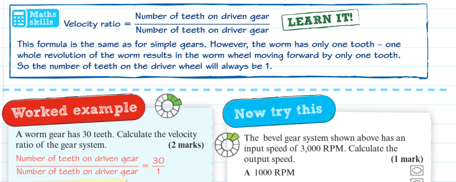 For calculating velocity ratios in worm gear systems, you use the standard formula but remember that the worm (driver gear) always has just one tooth.
Worked Example: Worm Gear Velocity Ratio
The velocity ratio equals the number of teeth on the worm wheel divided by 1:
If a worm wheel has 30 teeth, the velocity ratio is 30:1, meaning the worm must rotate 30 times to turn the worm wheel once.
Rack and pinion systems
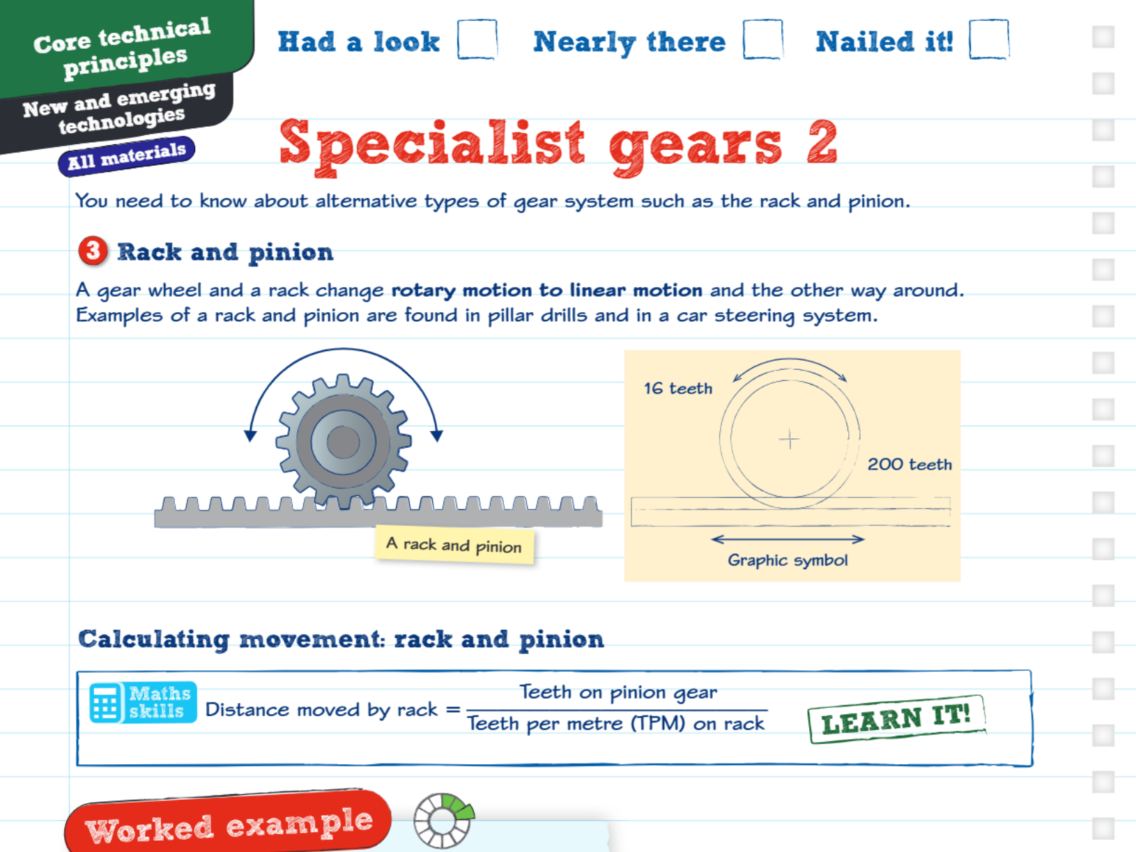
Rack and pinion mechanisms perform a completely different function from other gear systems - they convert rotary motion into linear motion, or vice versa. The pinion is a circular gear that meshes with a rack, which is essentially a straight gear with teeth arranged in a line.
 This conversion between rotary and linear motion makes rack and pinion systems extremely useful in applications like pillar drills (where rotating the handle moves the drill bit up and down) and car steering systems (where turning the steering wheel moves the wheels left and right).
To calculate how far a rack moves, you need to know two things: the number of teeth on the pinion gear and the teeth per metre (TPM) specification of the rack.
Worked Example: Rack Movement Calculation
The distance moved by the rack equals the number of teeth on the pinion divided by the teeth per metre on the rack:
If a pinion has 50 teeth and meshes with a rack that has 400 teeth per metre:
- Distance = metres (or 12.5 centimetres)
- One complete revolution of the pinion moves the rack 12.5 cm
The beauty of rack and pinion systems lies in their precision and reliability. They provide direct mechanical connection between rotary and linear motion without slippage, making them ideal for applications requiring accurate positioning.
Key Points to Remember:
- Bevel gears change the direction of rotary motion through 90 degrees and are found in hand drills and car differentials
- Worm and worm wheel systems create large speed reductions and prevent load fallback, making them perfect for security applications
- Rack and pinion mechanisms convert between rotary and linear motion, essential for steering systems and drilling equipment
- All specialist gears use similar velocity ratio calculations, but each has unique characteristics that make them suitable for specific applications
- Understanding the teeth per metre concept is crucial for calculating rack movement in rack and pinion systems