22.1 – Investigating Current and Voltage Relationships (Leaving Cert Physics): Revision Notes
22.1 – Investigating Current and Voltage Relationships
Aim of the experiment
This experiment allows us to verify the relationship between current flowing through an ohmic conductor and the voltage applied across it. The main goal is to demonstrate that current and voltage are directly proportional in materials that follow Ohm's Law.
Understanding ohmic conductors
An ohmic conductor is a material that obeys Ohm's Law, meaning the current flowing through it is directly proportional to the voltage applied across it, provided temperature remains constant. Most metals at constant temperature behave as ohmic conductors.
The key requirement for ohmic behaviour is that temperature must remain constant throughout the experiment. When temperature changes, the resistance of most conductors also changes, which can affect the linear relationship between current and voltage.
Equipment needed
The following apparatus is required for this investigation:
- DC power supply - provides variable voltage to the circuit
- Variable resistor (rheostat) - allows fine control of voltage across the test wire
- Resistance wire - the ohmic conductor being tested (often nichrome wire)
- Ammeter - measures current flowing through the circuit
- Voltmeter - measures voltage across the resistance wire
- Connecting leads - complete the electrical circuit
Each piece of equipment serves a specific purpose in creating accurate measurements. The ammeter must be connected in series to measure the actual current through the wire, while the voltmeter must be connected in parallel to measure the potential difference across the wire.
Circuit setup
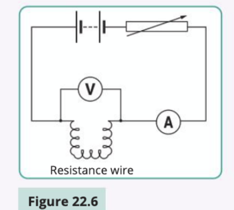
The circuit must be arranged carefully to obtain accurate measurements. The ammeter is connected in series with the resistance wire to measure the current flowing through it. The voltmeter is connected in parallel with the resistance wire to measure the voltage across it. The variable resistor allows you to control the voltage and current values systematically.
Critical Connection Rules:
- Voltmeter: Always connect in parallel with the component you're measuring
- Ammeter: Always connect in series with the circuit
- Incorrect connections will give wrong readings and may damage instruments
Experimental method
Follow these steps to investigate the current-voltage relationship:
Initial setup: Arrange the equipment according to the circuit diagram, ensuring the voltmeter is connected in parallel with the resistance wire and the ammeter is in series with the circuit.
Starting measurements: Adjust the variable resistor so that the voltage across the resistance wire starts at a small value. Record both the current reading from the ammeter and the voltage reading from the voltmeter.
Systematic data collection: Gradually increase the voltage by adjusting the variable resistor. For each voltage setting, record the corresponding current value. Take at least 6-8 measurements across a suitable range.
Repeat measurements: Take multiple readings at each voltage setting to improve reliability, then calculate average values.
Data recording: Create a table with columns for voltage (V) and current (I), ensuring all measurements are recorded in appropriate units.
Calculate resistance: For each voltage-current pair, calculate the resistance using .
Graph analysis: Plot a graph with current (I) on the y-axis and voltage (V) on the x-axis. The relationship should produce a straight line through the origin.
Why start with small values? Starting with low voltage and current values helps prevent the resistance wire from heating up significantly at the beginning of the experiment. This ensures the temperature remains as constant as possible throughout the measurements.
Results and graph interpretation
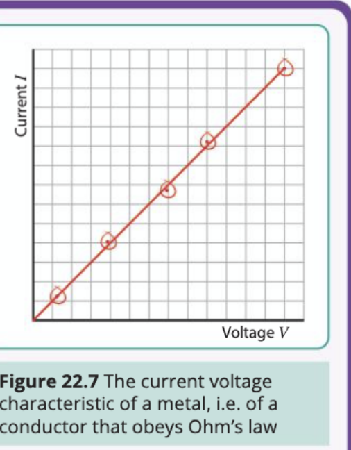
When you plot current against voltage, you should obtain a straight line passing through the origin. This linear relationship confirms that current is directly proportional to voltage, which is exactly what Ohm's Law predicts.
The gradient of this line equals , where R is the resistance of the wire. This means you can calculate the resistance by finding the slope of the line:
Resistance =
If your graph shows a straight line through the origin, this proves the wire is an ohmic conductor that follows Ohm's Law: .
Worked Example: Calculating Resistance from Graph
Step 1: Identify two points on your line
- Point 1: (2V, 0.4A)
- Point 2: (6V, 1.2A)
Step 2: Calculate the gradient Gradient = A/V
Step 3: Find resistance Resistance =
Key relationships and formulas
The fundamental relationship investigated in this experiment is Ohm's Law:
Where:
- = voltage (measured in volts, V)
- = current (measured in amperes, A)
- = resistance (measured in ohms, Ω)
This can be rearranged to find resistance:
Ohm's Law only applies to ohmic conductors at constant temperature. Non-ohmic conductors, such as diodes or filament bulbs, do not follow this linear relationship and will produce curved graphs instead of straight lines.
Sources of experimental error
Several factors can affect the accuracy of your results:
Circuit connections: Ensure your circuit is connected correctly, with the voltmeter in parallel with the resistance wire and the ammeter in series with the circuit. Poor connections can lead to inaccurate readings.
Current heating effects: Avoid using large current values, as the resistance wire will heat up and its resistance will change. This violates the constant temperature condition required for Ohm's Law.
Instrument sensitivity: Use sensitive, high-resistance voltmeters and sensitive ammeters to obtain accurate readings. Digital instruments are generally more precise than analogue ones.
Reading errors: Take care when reading instrument scales, and consider taking multiple readings at each measurement point to reduce random errors.
Most Critical Error to Avoid: Heating effects from excessive current are the most significant source of error in this experiment. High currents cause the resistance wire to heat up, changing its resistance and destroying the linear relationship you're trying to demonstrate. Always start with low values and increase gradually.
Exam tips
Essential Exam Points:
- Always draw circuit diagrams clearly, showing correct symbols for each component
- Remember that voltmeters measure potential difference across components (parallel connection)
- Remember that ammeters measure current through components (series connection)
- When describing the graph, state that it's a straight line through the origin, proving direct proportionality
- Be able to calculate resistance from both individual V and I values, and from the graph gradient
Key Points to Remember:
- Ohm's Law states that for ohmic conductors at constant temperature
- Current and voltage are directly proportional in ohmic conductors, producing a straight-line graph through the origin
- The voltmeter connects in parallel with the component, while the ammeter connects in series
- The resistance can be calculated from the gradient of the I-V graph as
- Heating effects from large currents can change resistance and affect results