23.1 – Investigating Current and Voltage in a Filament Lamp (Leaving Cert Physics): Revision Notes
23.1 – Investigating Current and Voltage in a Filament Lamp
Aim of the experiment
This experiment investigates how the current flowing through a filament lamp varies with the voltage applied across it. Since a filament lamp is a non-ohmic conductor, we expect to see a non-linear relationship between current and voltage, unlike the straight-line relationship seen with ohmic conductors.
Key Difference: Unlike ohmic conductors (such as resistors) that follow Ohm's law and produce straight-line I-V graphs, non-ohmic conductors like filament lamps show curved relationships due to their changing resistance.
Understanding non-ohmic conductors
A filament lamp is classified as a non-ohmic conductor because its resistance changes with temperature. As the voltage across the bulb increases, more current flows, causing the filament to heat up. This increased temperature causes the resistance of the filament to increase, which affects the current flow.
The tungsten filament inside the bulb experiences significant temperature changes during operation. At low voltages, the filament remains relatively cool and has low resistance. However, as the voltage increases, the filament can reach temperatures of over 2000°C, dramatically increasing its electrical resistance.
Equipment needed
To carry out this experiment, you will need:
- DC power supply (0-12 V)
- 12 V filament bulb
- Variable resistor (rheostat)
- Ammeter (to measure current)
- Voltmeter (to measure voltage)
- Connecting wires
Safety Consideration: Always check the voltage rating of your filament bulb before connecting the power supply. Exceeding the rated voltage can cause the bulb to blow and potentially create safety hazards.
Circuit setup
The circuit must be connected correctly to obtain accurate measurements:
- Connect the ammeter in series with the filament bulb to measure the current flowing through it
- Connect the voltmeter in parallel with the filament bulb to measure the voltage across it
- Include a variable resistor to control the voltage and current in the circuit
- Use the DC power supply as your voltage source
Common Circuit Mistakes to Avoid:
- Never connect the voltmeter in series with the bulb - this will give incorrect readings and may damage the metre
- Never connect the ammeter in parallel with the bulb - this will create a short circuit
- Always double-check your connections before switching on the power supply
Method and procedure
Follow these steps to investigate the current-voltage relationship:
-
Set up the circuit as shown in the circuit diagram, ensuring all connections are secure and correct
-
Adjust the rheostat (variable resistor) until the voltage across the bulb reads approximately 1 V
-
Record the measurements of both voltage (V) and current (I) in your data table
-
Increase the voltage by adjusting the rheostat, then record the new current value
-
Repeat the measurements for several different voltage values, recording all results in your table
-
Continue taking readings across a range of voltages from low to the maximum safe value
-
Plot your results on graph paper with current (I) on the y-axis and voltage (V) on the x-axis
Worked Example: Taking Measurements
Step 1: Set rheostat to give 1.0 V across the bulb
- Voltage reading: 1.0 V
- Current reading: 0.15 A
Step 2: Adjust rheostat to increase voltage to 2.0 V
- Voltage reading: 2.0 V
- Current reading: 0.25 A
Step 3: Continue increasing in regular intervals
- 3.0 V → 0.32 A
- 4.0 V → 0.37 A
- And so on...
Notice how the current increases become smaller as voltage increases.
Expected results
When you plot your current against voltage measurements, you should observe a curved line rather than a straight line. This curve demonstrates the non-ohmic nature of the filament lamp.
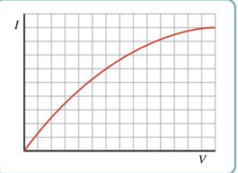
The characteristic features of this I-V curve are:
- Steep initial slope at low voltages when the filament is cool
- Gradual flattening of the curve at higher voltages as the filament heats up
- Non-linear relationship throughout the entire range
Graph Interpretation: The steepness of the curve at any point indicates the conductance of the filament at that operating condition. A steep curve means low resistance (high conductance), while a flatter curve indicates higher resistance.
Why the curve occurs
The curved relationship exists because:
- At low voltages, the filament is relatively cool, so its resistance is low and current increases rapidly with voltage
- As voltage increases, the filament temperature rises significantly
- Higher temperatures cause the resistance of the tungsten filament to increase
- This increased resistance means that further voltage increases produce smaller increases in current
- The result is a flattening curve rather than a straight line
This relationship can be understood through the temperature coefficient of resistance for tungsten. As temperature increases, the atoms in the tungsten lattice vibrate more vigorously, creating more obstacles to electron flow and increasing electrical resistance.
Sources of error
To ensure accurate results, be aware of these potential sources of error:
Critical Measurement Errors to Avoid:
Circuit setup errors:
- Ensure the voltmeter is connected in parallel with the bulb, not in series
- Check that the ammeter is in series with the bulb and battery
- Verify all connections are secure and making good contact
Measurement errors:
- Use sensitive, high-resistance voltmeters to avoid affecting the circuit
- Choose an appropriately sensitive ammeter for accurate current readings
- Take multiple readings and calculate averages to reduce random errors
- Allow the filament to cool between readings if taking measurements in reverse order
Environmental factors:
- Room temperature can affect initial resistance readings
- Vibrations can cause loose connections and fluctuating readings
Alternative investigation: If you replace the filament bulb with a thermistor, you can use the same equipment and procedure to investigate how temperature affects resistance in a different type of component.
Key physics concepts
This experiment demonstrates several important physics principles:
Non-ohmic behaviour: Components that don't obey Ohm's law show curved I-V characteristics rather than straight lines.
Temperature dependence: The resistance of many materials changes significantly with temperature, affecting their electrical properties.
Practical measurements: Real electrical measurements require careful consideration of how measuring instruments affect the circuits they're connected to.
Understanding these concepts is essential for analysing the behaviour of real electrical components, which often deviate from idealised theoretical models due to factors like temperature, material properties, and operating conditions.
Exam tips
Success in Examinations:
- Always label your axes clearly when drawing I-V graphs
- Remember that non-ohmic conductors produce curved graphs
- Be able to explain why the curve flattens at higher voltages
- Know the difference between series and parallel connections for ammeters and voltmeters
- Practice sketching the characteristic curve shape from memory
- Be prepared to calculate resistance at different points using
Key Points to Remember:
- Filament lamps are non-ohmic conductors - their resistance increases with temperature
- The I-V graph is curved - steep at low voltages, flattening at higher voltages
- Voltmeters go in parallel with components to measure voltage across them
- Ammeters go in series with components to measure current through them
- Temperature affects resistance - hotter filaments have higher resistance, causing the curved relationship
- The curve shape is predictable - always starts steep and gradually flattens due to increasing resistance