24.1 – Investigating Current and Voltage in a Semiconductor Diode (Leaving Cert Physics): Revision Notes
24.1 – Investigating Current and Voltage in a Semiconductor Diode
Objective
This experiment investigates how current flows through a semiconductor diode under different voltage conditions. You will explore the relationship between current and voltage when the diode is forward-biased (allowing current flow) and reverse-biased (blocking current flow).
A semiconductor diode is an electronic component that allows current to flow easily in one direction while blocking it in the opposite direction, making it essential for electronic circuits that need to control current direction.
What you need (equipment)
- Semiconductor diode (silicon type)
- Low-voltage DC power supply (0-20 V)
- Variable resistor (0-2 kΩ) for voltage control
- Milliammeter (0-20 mA) for forwards bias measurements
- Microammeter (0-10 μA) for reverse bias measurements
- High-resistance voltmeter (0-20 V)
- Connecting wires
- Graph paper for plotting results
The experiment requires two different types of ammeters because the current levels vary dramatically between forwards and reverse bias conditions. Forwards bias produces currents measured in milliamperes (mA), while reverse bias produces much smaller currents measured in microamperes (μA).
Circuit setup
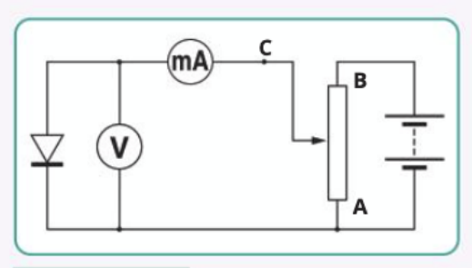
The experiment uses two different circuit configurations to measure the diode's behaviour accurately in both forwards and reverse bias conditions.
Method
Part 1: Forward-biased measurements
-
Set up the forwards bias circuit as shown in the diagram above, ensuring the diode allows current to flow (positive terminal of power supply connects to the diode's anode).
-
Take initial readings: With the variable resistor's movable terminal at position A, read both the voltage across the diode from the voltmeter and the corresponding current from the milliammeter. Record these values.
-
Increase voltage gradually: Adjust the variable resistor towards position B to increase the voltage across the diode by approximately 0.2 V. Measure and record the new voltage and current values.
-
Continue measurements: Repeat step 3 until the current reaches just below the manufacturer's maximum safe limit (typically 50 mA for most diodes).
Safety Warning: Never exceed the manufacturer's specified maximum forwards current (typically around 50 mA) to prevent permanent diode damage. Always monitor your current readings carefully during the experiment.
Part 2: Reverse-biased measurements
-
Reverse the diode connections so it becomes reverse-biased (positive terminal now connects to the diode's cathode).
-
Change the ammeter: Remove the milliammeter and connect the microammeter in the circuit. Important: The microammeter position differs from the milliammeter setup to ensure accurate readings.
-
Take reverse bias readings: Starting again with the variable resistor at position A, measure and record a series of voltage and current values. You can increase the voltage in larger steps this time since the current changes very little.
-
Plot your results: Create a graph with current (I) on the y-axis and voltage (V) on the x-axis. Use different scales for forwards bias (mA) and reverse bias (μA) sections.
Data collection
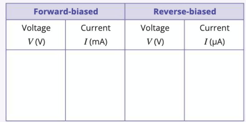
Use a table like this to organise your measurements systematically.
When recording your measurements, pay careful attention to the units. Forwards bias currents should be recorded in milliamperes (mA), while reverse bias currents should be recorded in microamperes (μA). This distinction is crucial for accurate data analysis.
Understanding your results
Forward-biased behaviour
When the diode is forward-biased, it exhibits two distinct regions:
-
Low voltage region: Below the junction voltage (~0.6 V for silicon diodes), very little current flows because the applied voltage isn't sufficient to overcome the diode's internal barrier.
-
Conduction region: Once the voltage exceeds the junction voltage, current increases dramatically with small voltage increases. This exponential relationship makes the diode an excellent one-way conductor.
Worked Example: Junction Voltage Behaviour
For a silicon diode at room temperature:
- At V = 0.5 V: Current ≈ 0.1 mA (very low)
- At V = 0.6 V: Current ≈ 1 mA (junction voltage reached)
- At V = 0.7 V: Current ≈ 10 mA (exponential increase)
- At V = 0.8 V: Current ≈ 30 mA (approaching maximum safe limit)
This demonstrates the sharp turn-on characteristic once the junction voltage of ~0.6 V is exceeded.
Reverse-biased behaviour
When reverse-biased, the diode acts like a very high-resistance component:
-
Leakage current region: Only an extremely small current (typically less than 1 μA) flows, called leakage current. This current remains nearly constant over a wide voltage range.
-
Breakdown region: If the reverse voltage becomes too high, the diode's insulating properties suddenly fail, causing destructive current flow that will damage the component.
Critical Concept: The dramatic difference in current levels between forwards and reverse bias is what makes diodes useful as rectifiers. Forwards bias: mA range; Reverse bias: μA range - a difference of three orders of magnitude!
Important experimental considerations
Why different ammeters?
The choice of ammeter depends on the expected current range:
-
Forward bias: The diode has very low resistance, allowing currents in the milliampere range that require a milliammeter for measurement.
-
Reverse bias: The diode has extremely high resistance, producing currents in the microampere range that need a sensitive microammeter.
Measurement accuracy tips
Understanding the circuit configuration is crucial for accurate measurements:
-
Voltmeter positioning: The high-resistance voltmeter draws negligible current, so its reading accurately represents the voltage across the diode in both bias conditions.
-
Forward bias circuit: The milliammeter reading directly represents the current through the diode because the voltmeter's current consumption is insignificant.
-
Reverse bias circuit: The microammeter must be positioned to measure only the diode current, not the total circuit current, ensuring accurate reverse current measurements.
Measurement Tip: In reverse bias, the tiny leakage current can be affected by temperature, humidity, and even static electricity. Handle the circuit carefully and take readings quickly to maintain accuracy.
Safety considerations
Protecting your equipment and ensuring accurate results requires careful attention to operating limits:
-
Maximum current: Never exceed the manufacturer's specified maximum forwards current (typically around 50 mA) to prevent permanent diode damage.
-
Maximum reverse voltage: Avoid applying excessive reverse voltage that could cause breakdown and destroy the diode.
-
Protective resistor: Consider adding a current-limiting resistor in series with the milliammeter to prevent accidental overcurrent damage.
Key characteristics of the I-V curve
The resulting graph shows the diode's characteristic I-V curve with these features:
- Sharp turn-on: Current increases exponentially once the junction voltage is reached
- Asymmetrical behaviour: Dramatically different current levels for forwards vs reverse bias
- Temperature dependence: Junction voltage and leakage current vary with temperature
- One-way conduction: Clearly demonstrates the diode's rectifying properties
Worked Example: Interpreting the I-V Curve
A typical silicon diode I-V curve shows:
Forward bias section:
- Flat region from 0 to ~0.6 V with minimal current
- Sharp exponential rise after 0.6 V
- Current in mA scale (e.g., 0-50 mA)
Reverse bias section:
- Nearly flat line with constant leakage current
- Current in μA scale (e.g., 0-10 μA)
- Demonstrates the "one-way valve" behaviour
Key Points to Remember:
- Diodes are directional components - they conduct significantly in only one direction (forwards bias)
- Junction voltage is approximately 0.6 V for silicon diodes - below this, forwards current is minimal
- Current scales differ dramatically - use mA for forwards bias, μA for reverse bias measurements
- Circuit configuration matters - ammeter placement affects measurement accuracy, especially in reverse bias
- Safety first - never exceed manufacturer specifications for current or voltage to avoid damaging the diode
- The I-V characteristic curve clearly demonstrates the diode's rectifying behaviour with exponential forwards conduction and minimal reverse current